3-Blink Turn Signal Relay Mod
#1
 04-12-2014, 10:18 PM


3-Blink Turn Signal Relay Mod
Disclaimer: Do this mod at your own risk. If you are unsure of your abilities, consult a professional.
This mod adds a relay to your car's turn signal system that allows the driver to just slightly press and release the turn signal stalk and have turn signal automatically blink three times.
A big thanks goes out to 6speed member jpflip for furnishing me with the wiring diagram.
The part is a VW/audi part, # 000-953-227A, available through many retailers.
Tools needed:
Pliers - I used needle nose, you can probably use others
T20 Torx driver
Flat screwdriver
Lisle 56500 terminal tool
Zipties
Optional:
Magnet tool
Electrical tape

First, you must remove the gauge cluster pod. This is pretty well documented elsewhere, so I'll keep it brief.
Press the Hazard switch, this will slightly expose two slots in the side of the button. Use these to pull the button out.
That will then expose two slots in the cavity that the button was in. Using a screwdriver, you can carefully pry the button trim out. Avoid prying against the plastic directly to prevent from marring the surface. I just put my hand between the screwdriver and the dash. It doesn't take that much force to get it loose.

That will expose one T20 Torx screw and the hazard switch.

Remove the Torx screw.
Remove the hazard switch by gripping the plastic carefully with the pliers. With your other hand, squeeze the two tabs at the sides of the switch and pull the switch with the pliers. Again, it doesn't take a ton of force.

On the left side of the gauge pod, pull the little grille that covers the hands free mic. This will expose another T20 Torx screw, remove it.

This is where the magnet comes in hand as to not drop the screw inside of the gauge pod.

Next, you will need to lift the gauge pod up off of the dash. There are six or so push clips that are holding it down. Just use your hands and work your way from one side to the other around the back.
Next you will need to release the hazard switch connector out of the pod. Press on the tab to the right of the connector and it should slide down from the pod.

There is a small yellow retaining clip that needs to be pulled out connector before the contacts can be removed. Just use the edge of a small flat screwdriver a press the retainer out from the top side.

OK, here comes the not so fun part.
The hazard relay has 9 contact locations (but only 8 contacts).
Insert the two smallest tines of the Lisle terminal tool into the connector housing so that the tines are on the outside of the contact that you want to pull. You need to push the tool firmly while tugging and wiggling the wire. Some come out with out a lot of effort, but a few of them took quite a bit of force. I'm sure there are better tools out there, but I was stuck with this one. It will do the job, but it's not fun, just be prepared for some pretty sore fingers.

Here's how the contacts are numbered.

And the diagram:
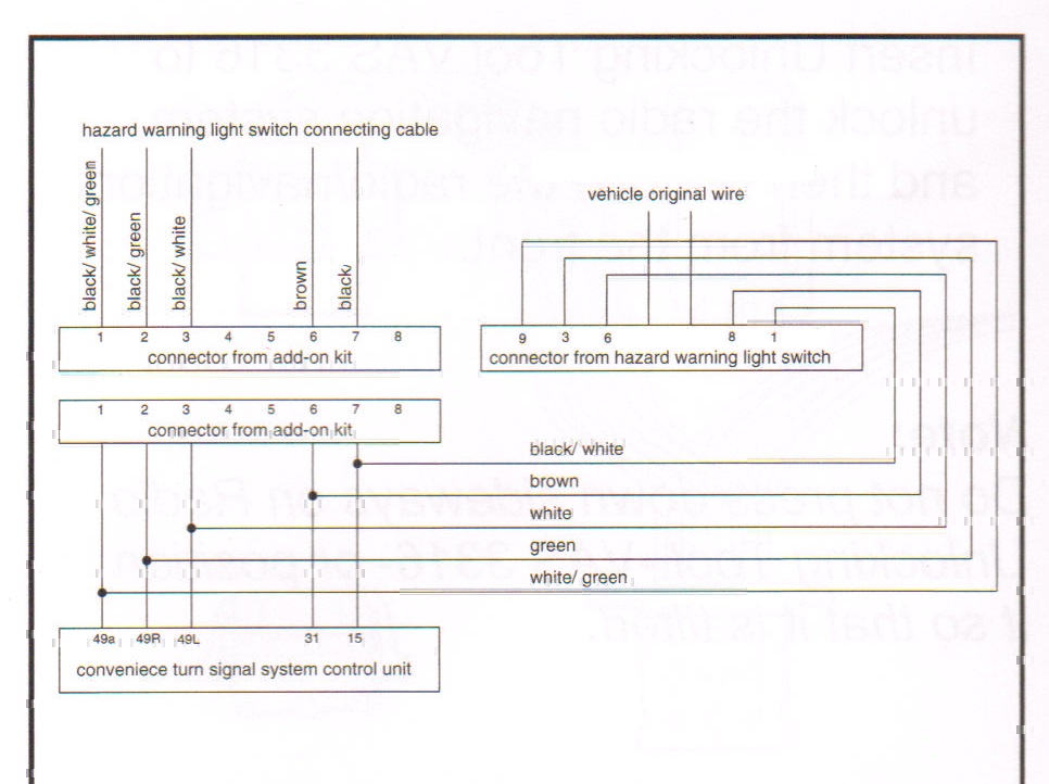
The loose connector that comes with the kit needs to be prepared by opening up the retaining tabs on both sides.
Start by removing contact 1 from the factory hazard switch connector.
Take the wire that was just removed from the hazard switch and insert it into position 7 on the loose connector.
Take the wire that's in position 7 on the mating connector and place it back into position 1 on the hazard switch connector.
Continue pulling one contact at a time and put it into the loose connector. Then take the corresponding wire from the kit and put it in the hazard switch.
When all of the connections are made, put the hazard switch in place and plug the 3-blink relay into the new socket. At this point, I would recommend that you test it to see if it works correctly. Turn the key to the on position and see if you were successful. When you're done testing, remove the hazard switch from it's connector. (they need to be separate to re-install in the car)
If everything is working correctly, you can now begin to put things back together. I found it was easier to remove the gauge pod completely at this point so that I could see what was going on in the dash. There are three connectors at the back of the pod. Press the tab in the middle of the connector and lift the black lever to release the connector. Release the other two connectors; the pod should now be free to remove.


There really isn't a lot of room to stuff all of the new wires/relay. What I decided to do was wrap the relay in some foam and stuff it and the wires into the dash. I did this to keep it from rattling around while driving.

Push the relay and the wires into the dash as deeply as you can.
Once that's done, start putting everything back together in reverse order. Don't forget to make sure all of the dash connectors are fully seated.
The way it works, I usually get 4 flashes rather than 3. Something about how the turn signal is interpreted by the relay. I have had a few instances where I get just one flash. I've found that it works best if you keep the stalk pressed for a half second or so before releasing it.
I'd be happy to answer any questions you might have.
Good luck and enjoy!
This mod adds a relay to your car's turn signal system that allows the driver to just slightly press and release the turn signal stalk and have turn signal automatically blink three times.
A big thanks goes out to 6speed member jpflip for furnishing me with the wiring diagram.
The part is a VW/audi part, # 000-953-227A, available through many retailers.
Tools needed:
Pliers - I used needle nose, you can probably use others
T20 Torx driver
Flat screwdriver
Lisle 56500 terminal tool
Zipties
Optional:
Magnet tool
Electrical tape
First, you must remove the gauge cluster pod. This is pretty well documented elsewhere, so I'll keep it brief.
Press the Hazard switch, this will slightly expose two slots in the side of the button. Use these to pull the button out.
That will then expose two slots in the cavity that the button was in. Using a screwdriver, you can carefully pry the button trim out. Avoid prying against the plastic directly to prevent from marring the surface. I just put my hand between the screwdriver and the dash. It doesn't take that much force to get it loose.
That will expose one T20 Torx screw and the hazard switch.
Remove the Torx screw.
Remove the hazard switch by gripping the plastic carefully with the pliers. With your other hand, squeeze the two tabs at the sides of the switch and pull the switch with the pliers. Again, it doesn't take a ton of force.
On the left side of the gauge pod, pull the little grille that covers the hands free mic. This will expose another T20 Torx screw, remove it.
This is where the magnet comes in hand as to not drop the screw inside of the gauge pod.
Next, you will need to lift the gauge pod up off of the dash. There are six or so push clips that are holding it down. Just use your hands and work your way from one side to the other around the back.
Next you will need to release the hazard switch connector out of the pod. Press on the tab to the right of the connector and it should slide down from the pod.
There is a small yellow retaining clip that needs to be pulled out connector before the contacts can be removed. Just use the edge of a small flat screwdriver a press the retainer out from the top side.
OK, here comes the not so fun part.
The hazard relay has 9 contact locations (but only 8 contacts).
Insert the two smallest tines of the Lisle terminal tool into the connector housing so that the tines are on the outside of the contact that you want to pull. You need to push the tool firmly while tugging and wiggling the wire. Some come out with out a lot of effort, but a few of them took quite a bit of force. I'm sure there are better tools out there, but I was stuck with this one. It will do the job, but it's not fun, just be prepared for some pretty sore fingers.
Here's how the contacts are numbered.
And the diagram:
The loose connector that comes with the kit needs to be prepared by opening up the retaining tabs on both sides.
Start by removing contact 1 from the factory hazard switch connector.
Take the wire that was just removed from the hazard switch and insert it into position 7 on the loose connector.
Take the wire that's in position 7 on the mating connector and place it back into position 1 on the hazard switch connector.
Continue pulling one contact at a time and put it into the loose connector. Then take the corresponding wire from the kit and put it in the hazard switch.
When all of the connections are made, put the hazard switch in place and plug the 3-blink relay into the new socket. At this point, I would recommend that you test it to see if it works correctly. Turn the key to the on position and see if you were successful. When you're done testing, remove the hazard switch from it's connector. (they need to be separate to re-install in the car)
If everything is working correctly, you can now begin to put things back together. I found it was easier to remove the gauge pod completely at this point so that I could see what was going on in the dash. There are three connectors at the back of the pod. Press the tab in the middle of the connector and lift the black lever to release the connector. Release the other two connectors; the pod should now be free to remove.
There really isn't a lot of room to stuff all of the new wires/relay. What I decided to do was wrap the relay in some foam and stuff it and the wires into the dash. I did this to keep it from rattling around while driving.
Push the relay and the wires into the dash as deeply as you can.
Once that's done, start putting everything back together in reverse order. Don't forget to make sure all of the dash connectors are fully seated.
The way it works, I usually get 4 flashes rather than 3. Something about how the turn signal is interpreted by the relay. I have had a few instances where I get just one flash. I've found that it works best if you keep the stalk pressed for a half second or so before releasing it.
I'd be happy to answer any questions you might have.
Good luck and enjoy!
Last edited by samx; 04-28-2014 at 03:25 PM. Reason: Add a note.

#3
04-13-2014, 07:10 AM
Kit part number
Thank you for great write up. Can you confirm part number on the box for the whole kit? I have the flasher part number as being 000 953 227A but the kit number on the box it all came in is 000 998 229A. Is this the same as yours?
Edit..the kit I have is correct and works great! Thank you! I don't know why I couldn't get it to work last time, but it works now! Thanks again!
Edit..the kit I have is correct and works great! Thank you! I don't know why I couldn't get it to work last time, but it works now! Thanks again!
Last edited by Vantaredoc; 04-13-2014 at 07:55 AM.
#4
04-28-2014, 02:52 PM
Registered User
Join Date: Mar 2012
Location: San Francisco & Pt Reyes Station California
Posts: 176
Rep Power: 29 

Helpful hints
Thanks to the previous posters who a) started the idea, b) made some (unsuccessful) attempts, and c) finally succeeded and wrote up a great DIY thread.
The following notes are my hints to add on to the process:
Hope this helps, and again, thanks to the whole community for making this mod come true.
I can attest that I positively love the mod. I use turn signals religiously, and like to be courteous when doing lane changes, and this mod works as advertised. It's virtually as good as the factory option on other cars.
The following notes are my hints to add on to the process:
- Remember to take out the yellow retaining plug. Do this by pressing in on the 3 yellow end-pieces of the retaining plug from the bottom of the hazard connector. The write-up above didn't mention this, so I was a bit frustrated until I found out that's what they were there for.
- To make the terminal removal process easier, bend in tines on the terminal removal tool with needle nose pliers. The terminals have small pieces of metal that are bent out, sort of like barbs. These tines on the terminal removal tool will have to press them in to allow for the terminals to be removed. Doing this mod on the removal tool tines will take the level of effort of terminal removal from a 9 to a 2.
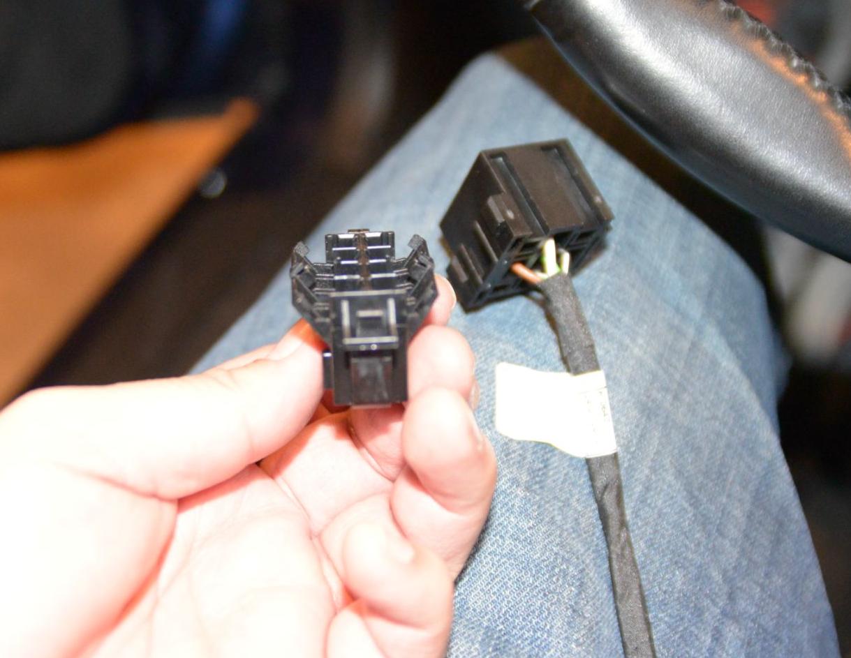
- When assembling, make sure you align the hazard connector correctly with the plug. It can go in either way, and my photo below shows the correct way.
- When you're doing this process, go ahead and remove all of the necessary terminals from the original hazard connector *before* you plug them into the new connector. It makes manipulation and removal of the remaining terminals in the hazard connector a lot easier.
Hope this helps, and again, thanks to the whole community for making this mod come true.
I can attest that I positively love the mod. I use turn signals religiously, and like to be courteous when doing lane changes, and this mod works as advertised. It's virtually as good as the factory option on other cars.
#5
04-28-2014, 03:24 PM
Thanks to the previous posters who a) started the idea, b) made some (unsuccessful) attempts, and c) finally succeeded and wrote up a great DIY thread.
The following notes are my hints to add on to the process:
Hope this helps, and again, thanks to the whole community for making this mod come true.
I can attest that I positively love the mod. I use turn signals religiously, and like to be courteous when doing lane changes, and this mod works as advertised. It's virtually as good as the factory option on other cars.
The following notes are my hints to add on to the process:
- Remember to take out the yellow retaining plug. Do this by pressing in on the 3 yellow end-pieces of the retaining plug from the bottom of the hazard connector. The write-up above didn't mention this, so I was a bit frustrated until I found out that's what they were there for.
- To make the terminal removal process easier, bend in tines on the terminal removal tool with needle nose pliers. The terminals have small pieces of metal that are bent out, sort of like barbs. These tines on the terminal removal tool will have to press them in to allow for the terminals to be removed. Doing this mod on the removal tool tines will take the level of effort of terminal removal from a 9 to a 2.
- When assembling, make sure you align the hazard connector correctly with the plug. It can go in either way, and my photo below shows the correct way.
- When you're doing this process, go ahead and remove all of the necessary terminals from the original hazard connector *before* you plug them into the new connector. It makes manipulation and removal of the remaining terminals in the hazard connector a lot easier.
Hope this helps, and again, thanks to the whole community for making this mod come true.
I can attest that I positively love the mod. I use turn signals religiously, and like to be courteous when doing lane changes, and this mod works as advertised. It's virtually as good as the factory option on other cars.
I hope you don't mind, but I borrowed your pic for the writeup.
Thanks.
#6
04-28-2014, 03:56 PM
Registered User
Join Date: Mar 2012
Location: San Francisco & Pt Reyes Station California
Posts: 176
Rep Power: 29 This project was truly a community effort with you being the key driver. Thanks!

Trending Topics
#8
05-01-2014, 01:31 PM
Registered User
Join Date: Mar 2012
Location: San Francisco & Pt Reyes Station California
Posts: 176
Rep Power: 29
I'm probably the least mechanically inclined of the people in this thread, and it took me about two hours. 45 minutes of that was googling and figuring out that there was actually a yellow clip that retains the terminals in the plug. Also, my wife catered in several glasses of champagne while I was working (hey, it's a Porsche, why not champagne).
But with what I know now, it'd probably take me about 50 minutes total, if I remember the keys:
Note: I did disconnect the battery before I did this (google 996 battery removal, because you have to turn the key to ACC position before you do it). I kind of freaked out when I plugged the battery back end, but eventually everything sorted itself out. Also, I initially plugged the harness in upside down. This led to the behavior of my hazards going whenever I used a turn signal. So, I flipped the harness, and all was good.
Have fun. The benefits are great, and it's kind of fun.
But with what I know now, it'd probably take me about 50 minutes total, if I remember the keys:
- Remove the yellow retaining clip.
- Bend the tips of the extraction tool in (this is a very key timesaver, and potential wire saver as you struggle with the terminals).
- Remove all terminals from the original harness plug *before* putting them into the newly supplied holder.
Note: I did disconnect the battery before I did this (google 996 battery removal, because you have to turn the key to ACC position before you do it). I kind of freaked out when I plugged the battery back end, but eventually everything sorted itself out. Also, I initially plugged the harness in upside down. This led to the behavior of my hazards going whenever I used a turn signal. So, I flipped the harness, and all was good.
Have fun. The benefits are great, and it's kind of fun.
Last edited by Empyreal; 05-01-2014 at 01:34 PM.
#9
05-19-2014, 06:07 AM
Did this yesterday and it went quite well. Thanks for posting the DIY!
One note, the hazard switch installs with the pins "upside down" compared to the PIN numbers. I had a moment when I installed it using Pin 1 to 1 and the hazards did not work. Only after I flipped it around and ignored the pin numbers did all work as expected. I tried using the instructions from the post above where the "hole" in the hazard switch is put on the same side as the large yellow locking pins, but - my switch had a hole on both sides - so that didn't work.
From my VW days I already had a decent removal tool for the wiring from the plugs, so that was quite easy. Anyone local is welcome to borrow this tool.

Thread
Thread Starter
Forum
Replies
Last Post
adnanm3
Aston Martin
17
11-22-2023 02:43 AM