
Porsche 914 Racecar

Thread Starter
|
Registered User
Joined: Sep 2010
Posts: 64
From: Hillsboro, OR
Rep Power: 18

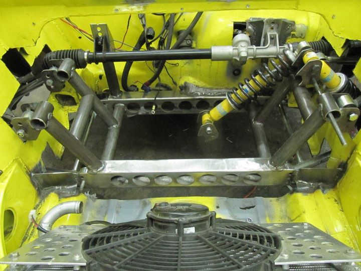
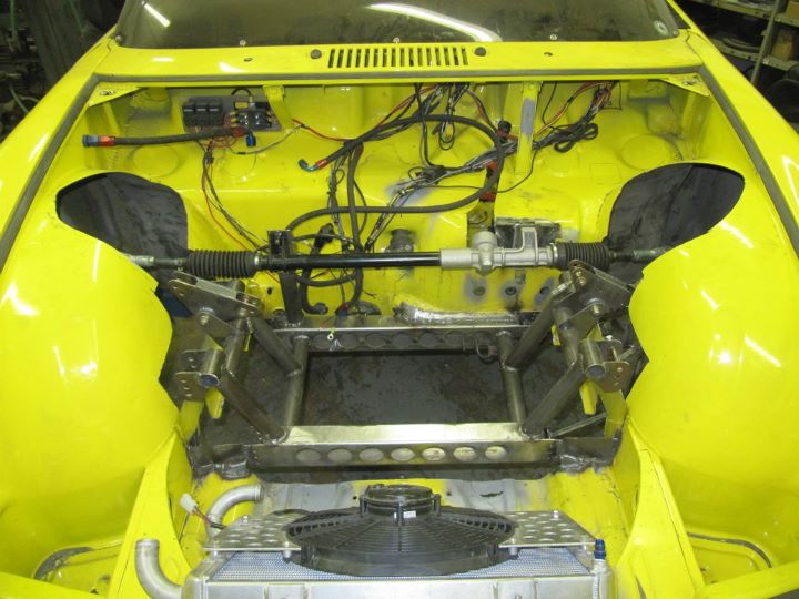
Placement ideas for the front shocks. No, I won't be running two shocks...the outer shock will be replaced by an adjustable push rod and a rocker assembly will be designed and installed in this approximate arrangement.
Thread Starter
|
Registered User
Joined: Sep 2010
Posts: 64
From: Hillsboro, OR
Rep Power: 18
I have a few additional parts to design and make before completely finishing the front assembly. I will then move on to the rear as I believe that it will be a bit more challenging. With both ends completed, I will cut out the existing cage and built a new one that ties everything together.
I will keep posting updates here if you are interested.
-Britain
I will keep posting updates here if you are interested.
-Britain

Any particular reason for abandoning the Porsche motor? The pursuit of horsepower rather than keeping the car in a particular class for racing? The Japanese alternatives are probably more plentiful and less expensive than an upgraded Porsche powerplant.
Not familiar at all with the 914 - just curious
Not familiar at all with the 914 - just curious
Thread Starter
|
Registered User
Joined: Sep 2010
Posts: 64
From: Hillsboro, OR
Rep Power: 18
Actually...the reasoning has to do with the SCCA Autocross rules. They favor small displacement turbocharged engines over larger displacement engines because all the minimum weight calculations are based on displacement.
For example, a 2.8L Porsche engine can make ~250hp while the 2.0L Turbo Subaru engine has the effective displacement of 2.8L (with the 1.4x multiplier for forced induction) and it makes ~400hp. You just can't get the power to displacement ratio down with a Porsche powerplant.
-Britain
For example, a 2.8L Porsche engine can make ~250hp while the 2.0L Turbo Subaru engine has the effective displacement of 2.8L (with the 1.4x multiplier for forced induction) and it makes ~400hp. You just can't get the power to displacement ratio down with a Porsche powerplant.
-Britain


Thread Starter
|
Registered User
Joined: Sep 2010
Posts: 64
From: Hillsboro, OR
Rep Power: 18
Ah yes...lots of updates...here you go.
Just got back from another 4 days in sunny SoCal working on the racecar. 12-15hrs days, but we got a lot done. Check it out.
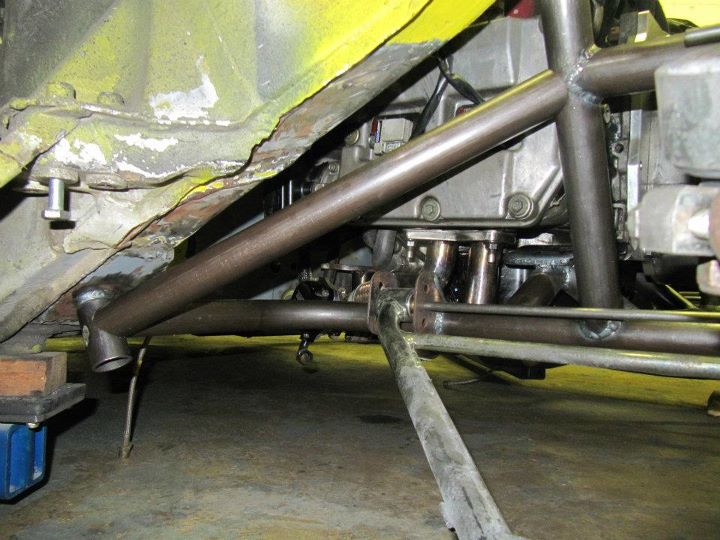
Lower bars of the rear sub-frame completed. These two bars took 5 attempted to get right. They had to contact 4 points with two compound bends and angled cuts. They intersect the frame rails in the front and the transmission mounts in the back.
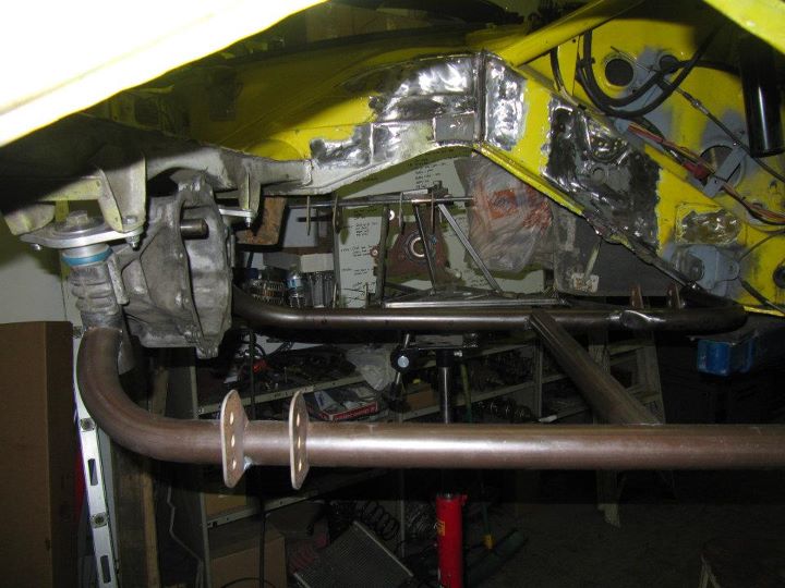
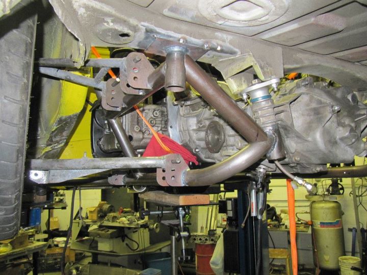
Side view of the lower sub-frame in place without the engine and transmission in place. Used an extra 901 nosecone to locate the transmission mounts.
Jigs in place to locate the proper pick-ups points for the upper mounts. The upper mounts are in-board 1/4" to achieve more negative camber compared to a stock lotus.
Rear suspension control arms in place at the upper pick-up point. Additional rear body mount added for the upper mount bar to hit the chassis.
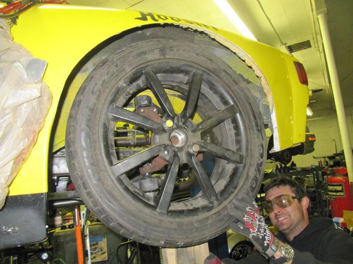
Rear Lotus wheel mounted on the car.
Just got back from another 4 days in sunny SoCal working on the racecar. 12-15hrs days, but we got a lot done. Check it out.
Lower bars of the rear sub-frame completed. These two bars took 5 attempted to get right. They had to contact 4 points with two compound bends and angled cuts. They intersect the frame rails in the front and the transmission mounts in the back.
Side view of the lower sub-frame in place without the engine and transmission in place. Used an extra 901 nosecone to locate the transmission mounts.
Jigs in place to locate the proper pick-ups points for the upper mounts. The upper mounts are in-board 1/4" to achieve more negative camber compared to a stock lotus.
Rear suspension control arms in place at the upper pick-up point. Additional rear body mount added for the upper mount bar to hit the chassis.
Rear Lotus wheel mounted on the car.
Thread Starter
|
Registered User
Joined: Sep 2010
Posts: 64
From: Hillsboro, OR
Rep Power: 18
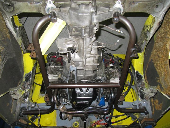
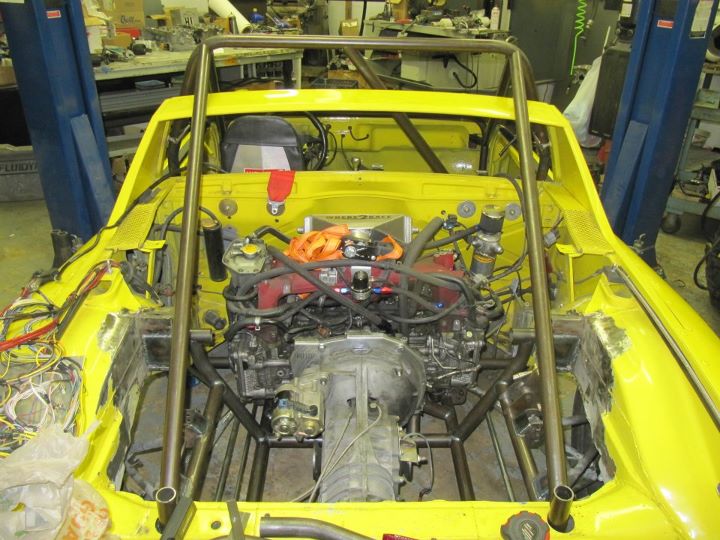
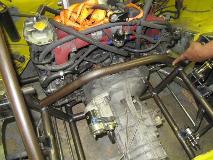
The rear sub-frame will also be a cradle for the engine mounts. This will free up some much needed room in the front of the engine. These utilize the stock Subaru engine mount parts with a few modifications.
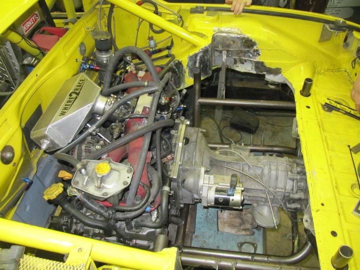
Engine in place in the new sub-frame and bolted to the car. There will be an additional cross-bar in place between the frame rails.
The sub-frame will unbolt from the car and the engine, transmission, and rear suspension will come out as one piece.
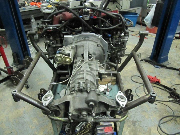
Side view of the sub-frame. The will be an additional bar across the front of the engine to support the turbo and other items that used to be mounted to the old crossbar.
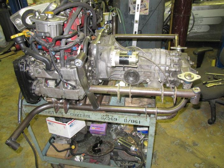
Completed rear sub-frame in place in the car for final welding. Here you can see the new engine mounts.
Engine in place in the new sub-frame and bolted to the car. There will be an additional cross-bar in place between the frame rails.
The sub-frame will unbolt from the car and the engine, transmission, and rear suspension will come out as one piece.
Side view of the sub-frame. The will be an additional bar across the front of the engine to support the turbo and other items that used to be mounted to the old crossbar.
Completed rear sub-frame in place in the car for final welding. Here you can see the new engine mounts.
Thread Starter
|
Registered User
Joined: Sep 2010
Posts: 64
From: Hillsboro, OR
Rep Power: 18
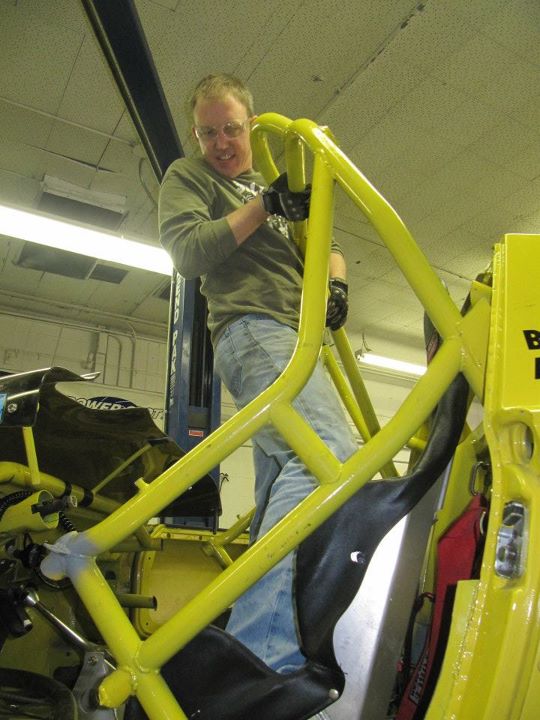
I knew the day would come sooner or later, but here we are cutting out the old cage.
The old cage was 1.75" x 0.120" and weighed in at 92lbs. It was a bit heavy as you can tell from my expression here.
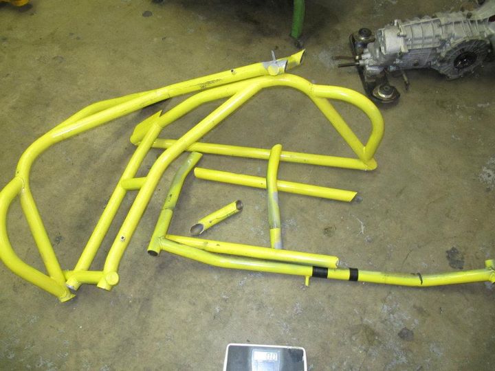
Pile of bars from the old cage. 92lbs of steel sitting here. I estimate that the new cage will be approximately 50lbs.
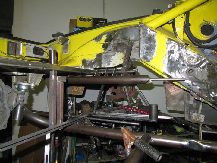
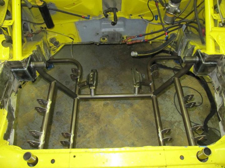
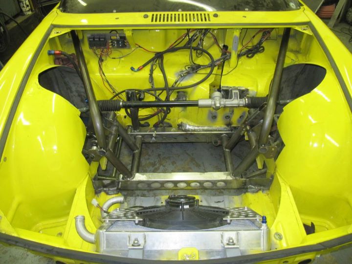
View from the rear without the cage. The new cage will tie in the frame rails as well as the two bars sticking up in the rear which are the upper sub-frame mounts.
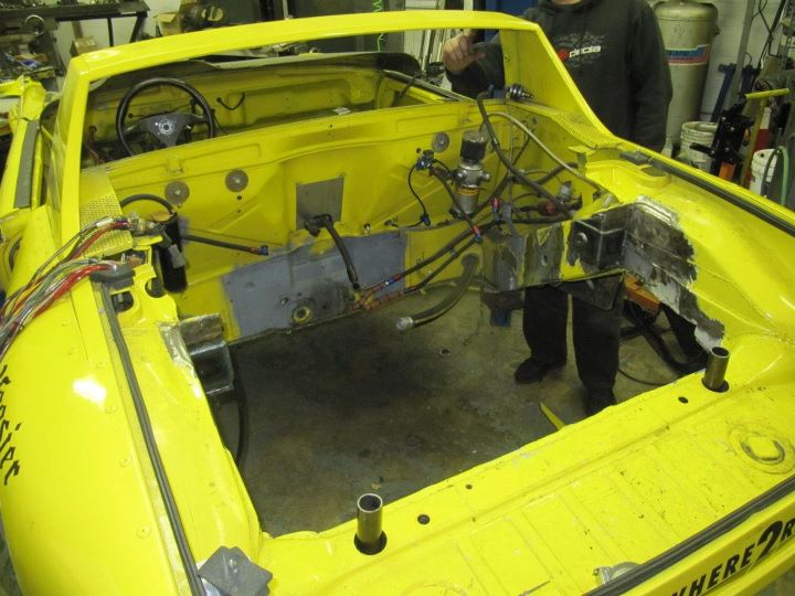
Additional structure related to the old suspension cut out of the front. Material will be added back to the wheel wells and the cage will extend forward to pick-up the front suspension assembly.
Lotus steering rack in place and excess 914 sheet metal removed.
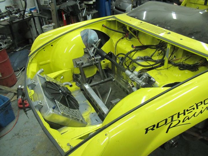
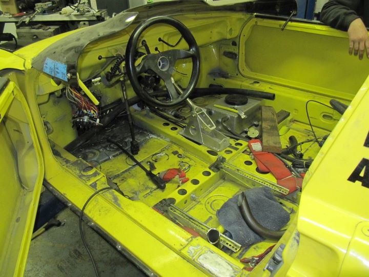
Lots more room in the car with the cage removed.
Next step is to construct the new cage and start putting the car back together.
-Britain
The old cage was 1.75" x 0.120" and weighed in at 92lbs. It was a bit heavy as you can tell from my expression here.
Pile of bars from the old cage. 92lbs of steel sitting here. I estimate that the new cage will be approximately 50lbs.
View from the rear without the cage. The new cage will tie in the frame rails as well as the two bars sticking up in the rear which are the upper sub-frame mounts.
Additional structure related to the old suspension cut out of the front. Material will be added back to the wheel wells and the cage will extend forward to pick-up the front suspension assembly.
Lotus steering rack in place and excess 914 sheet metal removed.
Lots more room in the car with the cage removed.
Next step is to construct the new cage and start putting the car back together.
-Britain

Thread Starter
|
Registered User
Joined: Sep 2010
Posts: 64
From: Hillsboro, OR
Rep Power: 18
Sorry about the lack of updates. I have since made two trips back down to California to work on the car and have made pretty good progress. As always, I had hoped to be further along at this point that I am but I am about 90% there.
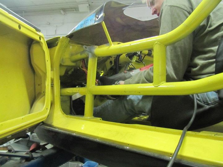
First off, the new cage is coming together nicely. The regulations to get my head under the cage and to meet the broomstick rule forced me to mount the seat lower and farther back and raise both the main hoop and the a-piller bar under the windscreen.
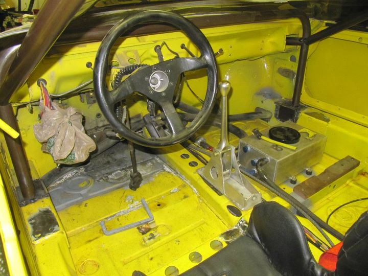
Here is the ****pit area.
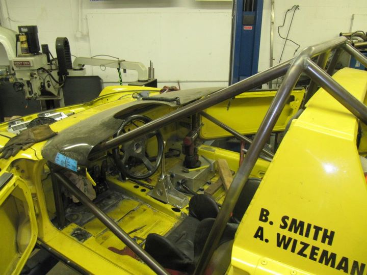
You can see how high the front a-piller bar is now.
The raised main hoop and the rules around the downbars forced me to either cut the targa bar or go over it...I decided to go over it and pick-up the rear suspension point.
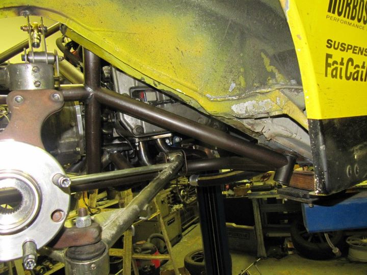
In the front, two bars extend from the top of the a-piller to the front suspension sub-frame. There will be two additional bars from the lower part of the a-piller forward that still need to get done.
First off, the new cage is coming together nicely. The regulations to get my head under the cage and to meet the broomstick rule forced me to mount the seat lower and farther back and raise both the main hoop and the a-piller bar under the windscreen.
Here is the ****pit area.
You can see how high the front a-piller bar is now.
The raised main hoop and the rules around the downbars forced me to either cut the targa bar or go over it...I decided to go over it and pick-up the rear suspension point.
In the front, two bars extend from the top of the a-piller to the front suspension sub-frame. There will be two additional bars from the lower part of the a-piller forward that still need to get done.
Thread Starter
|
Registered User
Joined: Sep 2010
Posts: 64
From: Hillsboro, OR
Rep Power: 18
Back on the rear sub-frame. Additional bars added to the rear lower subframe to strenghten the structure and triangulate everything.
And the other side.
A bar was added over the transmission and tie in the two sides of the rear sub-frame.
Another bar under the rear of the transmission that can also serve as a jack-point.
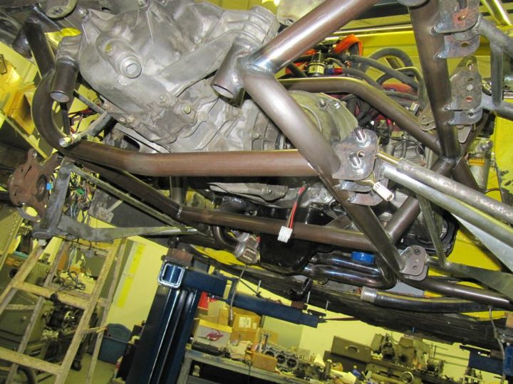
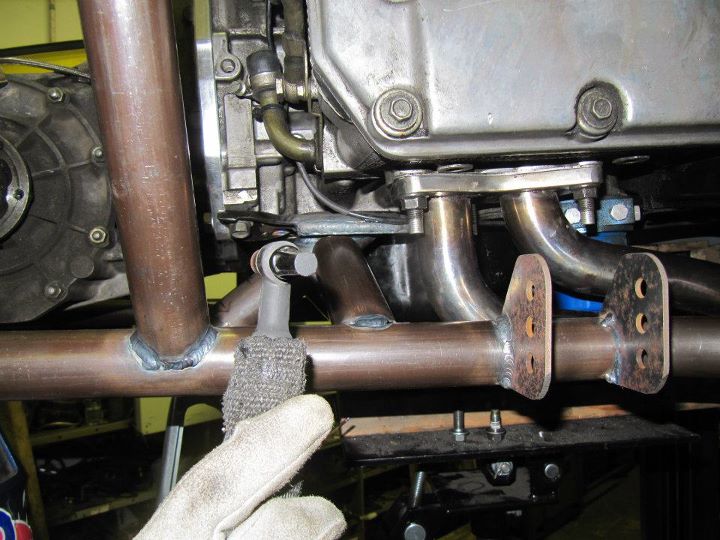
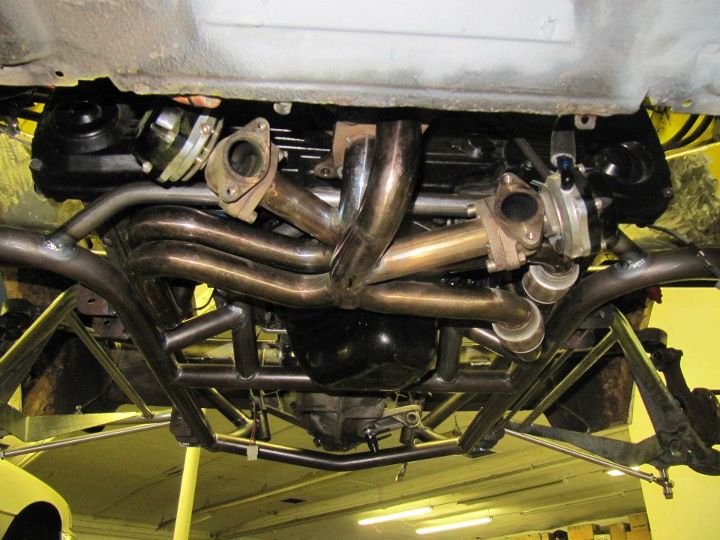
And finally a turbo mount bar that snakes up above the header and will help tie together the subframe.
And the other side.
A bar was added over the transmission and tie in the two sides of the rear sub-frame.
Another bar under the rear of the transmission that can also serve as a jack-point.
And finally a turbo mount bar that snakes up above the header and will help tie together the subframe.
Thread Starter
|
Registered User
Joined: Sep 2010
Posts: 64
From: Hillsboro, OR
Rep Power: 18
It is always the small stuff that takes up all the time. I had to make a new seat bracket, relocate the pedal assembly, make a hold for the dash off the a-piller bar and a couple of other small things.
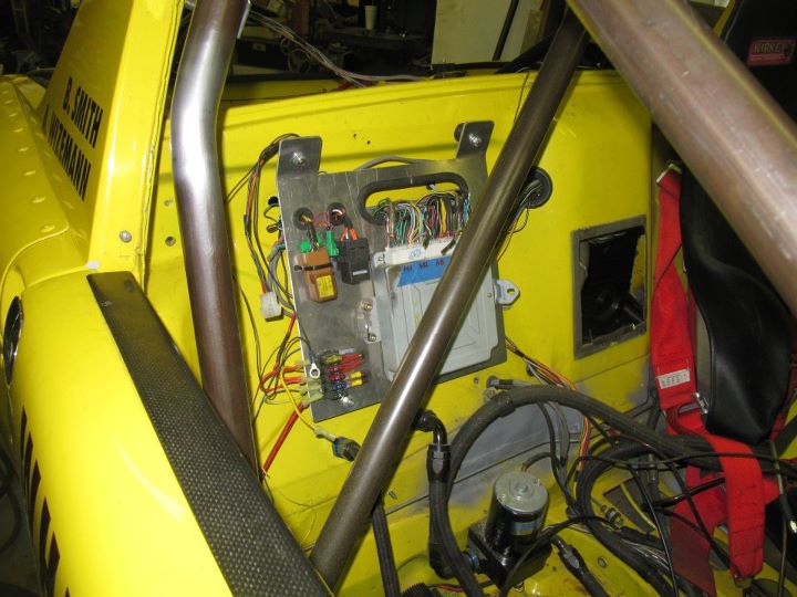
Here is the relocated the ECU to the passenger firewall. I will need to construct a nice cover to keep it out of the elements. Fortunately I only had to rewire a handful of the wires to move it and the old panel worked perfectly.
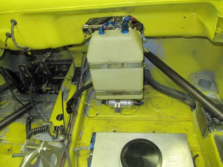
Fuel tank relocated to the passenger footwell with the fuel pump mounted right under it. This will keep it out of the heat from the radiator. I will need to construct a bulkhead to comply with the rules.
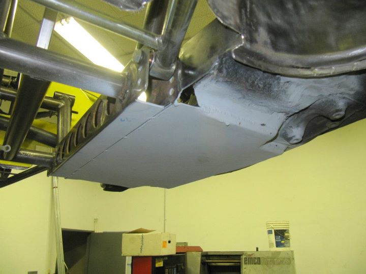
New front trunk floor. This panel is structural to hold the front of the car together.
Here is the relocated the ECU to the passenger firewall. I will need to construct a nice cover to keep it out of the elements. Fortunately I only had to rewire a handful of the wires to move it and the old panel worked perfectly.
Fuel tank relocated to the passenger footwell with the fuel pump mounted right under it. This will keep it out of the heat from the radiator. I will need to construct a bulkhead to comply with the rules.
New front trunk floor. This panel is structural to hold the front of the car together.