997 Turbo / GT2 2006–2012 Turbo discussion on the 997 model Porsche 911 Twin Turbo.
Sponsored by:
Sponsored by: Bears Transport

Vacuum routing/diagram

Thread Tools
 
Search this Thread
 
Rate Thread
 
  #1  
Old 04-02-2019, 06:10 AM
turboslut's Avatar
Registered User
Thread Starter
Join Date: Aug 2014
Location: Fort Lauderdale
Posts: 785
Rep Power: 60
turboslut has a brilliant futureturboslut has a brilliant futureturboslut has a brilliant futureturboslut has a brilliant futureturboslut has a brilliant futureturboslut has a brilliant futureturboslut has a brilliant futureturboslut has a brilliant futureturboslut has a brilliant futureturboslut has a brilliant futureturboslut has a brilliant future
Vacuum routing/diagram

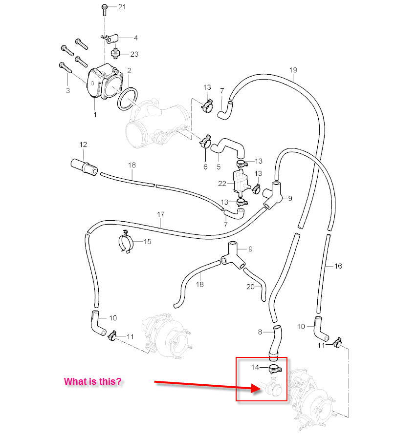
Hello, does anyone have a vacuum diagram for a 997 Turbo?

Electronic valves...are there one or two? I know there is one behind plenum that plumbs the diverter valves and the AIR system. Is there another one somewhere else like in the 996 turbo?
 
  #2  
Old 04-02-2019, 08:04 AM
turboslut's Avatar
Registered User
Thread Starter
Join Date: Aug 2014
Location: Fort Lauderdale
Posts: 785
Rep Power: 60
turboslut has a brilliant futureturboslut has a brilliant futureturboslut has a brilliant futureturboslut has a brilliant futureturboslut has a brilliant futureturboslut has a brilliant futureturboslut has a brilliant futureturboslut has a brilliant futureturboslut has a brilliant futureturboslut has a brilliant futureturboslut has a brilliant future
 
  #3  
Old 04-02-2019, 08:05 AM
turboslut's Avatar
Registered User
Thread Starter
Join Date: Aug 2014
Location: Fort Lauderdale
Posts: 785
Rep Power: 60
turboslut has a brilliant futureturboslut has a brilliant futureturboslut has a brilliant futureturboslut has a brilliant futureturboslut has a brilliant futureturboslut has a brilliant futureturboslut has a brilliant futureturboslut has a brilliant futureturboslut has a brilliant futureturboslut has a brilliant futureturboslut has a brilliant future
Question: Should vacuum be strong enough to suck on my palm if I remove the oil filler cap and place my hand on it?
 
  #4  
Old 04-02-2019, 10:24 AM
TT.BRN's Avatar
Registered User
Join Date: Oct 2010
Location: Bahrain
Posts: 433
Rep Power: 63
TT.BRN has a reputation beyond reputeTT.BRN has a reputation beyond reputeTT.BRN has a reputation beyond reputeTT.BRN has a reputation beyond reputeTT.BRN has a reputation beyond reputeTT.BRN has a reputation beyond reputeTT.BRN has a reputation beyond reputeTT.BRN has a reputation beyond reputeTT.BRN has a reputation beyond reputeTT.BRN has a reputation beyond reputeTT.BRN has a reputation beyond repute
That's the fuel pressure regulator on the passenger side rail ....

at idle vacuum should be around -0.6 bar (-8.5psi) ...
 
  #5  
Old 04-02-2019, 12:06 PM
turboslut's Avatar
Registered User
Thread Starter
Join Date: Aug 2014
Location: Fort Lauderdale
Posts: 785
Rep Power: 60
turboslut has a brilliant futureturboslut has a brilliant futureturboslut has a brilliant futureturboslut has a brilliant futureturboslut has a brilliant futureturboslut has a brilliant futureturboslut has a brilliant futureturboslut has a brilliant futureturboslut has a brilliant futureturboslut has a brilliant futureturboslut has a brilliant future
Originally Posted by TT.BRN
That's the fuel pressure regulator on the passenger side rail ....

at idle vacuum should be around -0.6 bar (-8.5psi) ...

Should I get -8.5psi at the oil filler cap with the car idling?
 
  #6  
Old 04-02-2019, 12:08 PM
turboslut's Avatar
Registered User
Thread Starter
Join Date: Aug 2014
Location: Fort Lauderdale
Posts: 785
Rep Power: 60
turboslut has a brilliant futureturboslut has a brilliant futureturboslut has a brilliant futureturboslut has a brilliant futureturboslut has a brilliant futureturboslut has a brilliant futureturboslut has a brilliant futureturboslut has a brilliant futureturboslut has a brilliant futureturboslut has a brilliant futureturboslut has a brilliant future
Where does this line go to on the other side? Should get full vacuum here as well?
 
Attached Thumbnails Click image for larger version

Name:	photo83.jpg
Views:	244
Size:	1.05 MB
ID:	532290  
  #7  
Old 04-02-2019, 06:07 PM
turboslut's Avatar
Registered User
Thread Starter
Join Date: Aug 2014
Location: Fort Lauderdale
Posts: 785
Rep Power: 60
turboslut has a brilliant futureturboslut has a brilliant futureturboslut has a brilliant futureturboslut has a brilliant futureturboslut has a brilliant futureturboslut has a brilliant futureturboslut has a brilliant futureturboslut has a brilliant futureturboslut has a brilliant futureturboslut has a brilliant futureturboslut has a brilliant future
Does anyone know where the hardline that the circled hose is feeding ends up on the other side?
 
Attached Thumbnails Click image for larger version

Name:	photo806.jpg
Views:	519
Size:	1.21 MB
ID:	532327  
  #8  
Old 04-02-2019, 08:21 PM
TT.BRN's Avatar
Registered User
Join Date: Oct 2010
Location: Bahrain
Posts: 433
Rep Power: 63
TT.BRN has a reputation beyond reputeTT.BRN has a reputation beyond reputeTT.BRN has a reputation beyond reputeTT.BRN has a reputation beyond reputeTT.BRN has a reputation beyond reputeTT.BRN has a reputation beyond reputeTT.BRN has a reputation beyond reputeTT.BRN has a reputation beyond reputeTT.BRN has a reputation beyond reputeTT.BRN has a reputation beyond reputeTT.BRN has a reputation beyond repute
Scavenge pump / brake booster
 
  #9  
Old 04-03-2019, 07:55 AM
turboslut's Avatar
Registered User
Thread Starter
Join Date: Aug 2014
Location: Fort Lauderdale
Posts: 785
Rep Power: 60
turboslut has a brilliant futureturboslut has a brilliant futureturboslut has a brilliant futureturboslut has a brilliant futureturboslut has a brilliant futureturboslut has a brilliant futureturboslut has a brilliant futureturboslut has a brilliant futureturboslut has a brilliant futureturboslut has a brilliant futureturboslut has a brilliant future
Update:

The green circled hose was not pushed in all the way into the hardline; the car is now 90% better. Night and day in the drivability dept. I think the DME must compensate for the parasitic drag created by increasing pump work as it creates vacuum during braking/decel. The leak at the junction was not letting the pump create the vacuum, and it was overcompensating and creating that weird decel idle hunt I put in the video.


My car is 97k miles strong, and I want to test all these vacuum only lines thoroughly.

Could I bother anyone on here to meaure the vacuum created by your pump? It looks like it should be easy to do by pulling out the hard line from the T junction and attaching a vacuum gauge there to test the negative pressure at idel, 2k pm and 4k rpm.

I will do it on my car and post video for comparison.


Also, another dumb question:

Should I be able to attach a vacuum pump/gauge to one of the diverter valve lines and pull and hold -10psi?


Thanks for the help so far guys.
 
  #10  
Old 04-06-2019, 09:22 AM
turboslut's Avatar
Registered User
Thread Starter
Join Date: Aug 2014
Location: Fort Lauderdale
Posts: 785
Rep Power: 60
turboslut has a brilliant futureturboslut has a brilliant futureturboslut has a brilliant futureturboslut has a brilliant futureturboslut has a brilliant futureturboslut has a brilliant futureturboslut has a brilliant futureturboslut has a brilliant futureturboslut has a brilliant futureturboslut has a brilliant futureturboslut has a brilliant future
Well over 30in if vacuum direct off the pump, is what I measured.


Does anyone know the logic for that changeover valve? When does it get activated and connected to plenum/diverter valve pressure?
 
  #11  
Old 04-17-2019, 12:16 PM
turboslut's Avatar
Registered User
Thread Starter
Join Date: Aug 2014
Location: Fort Lauderdale
Posts: 785
Rep Power: 60
turboslut has a brilliant futureturboslut has a brilliant futureturboslut has a brilliant futureturboslut has a brilliant futureturboslut has a brilliant futureturboslut has a brilliant futureturboslut has a brilliant futureturboslut has a brilliant futureturboslut has a brilliant futureturboslut has a brilliant futureturboslut has a brilliant future
Does anyone know the logic for that changeover valve? When does it get activated and connected to plenum/diverter valve pressure?
 
  #12  
Old 04-18-2019, 01:20 AM
TT.BRN's Avatar
Registered User
Join Date: Oct 2010
Location: Bahrain
Posts: 433
Rep Power: 63
TT.BRN has a reputation beyond reputeTT.BRN has a reputation beyond reputeTT.BRN has a reputation beyond reputeTT.BRN has a reputation beyond reputeTT.BRN has a reputation beyond reputeTT.BRN has a reputation beyond reputeTT.BRN has a reputation beyond reputeTT.BRN has a reputation beyond reputeTT.BRN has a reputation beyond reputeTT.BRN has a reputation beyond reputeTT.BRN has a reputation beyond repute
DV's cant stay shut under their own spring power. Valve helps the spring by switching pressures. On tiptronics, the vac line from the Bb line also supplies gear coolant valve .
 
  #13  
Old 04-20-2019, 11:23 AM
turboslut's Avatar
Registered User
Thread Starter
Join Date: Aug 2014
Location: Fort Lauderdale
Posts: 785
Rep Power: 60
turboslut has a brilliant futureturboslut has a brilliant futureturboslut has a brilliant futureturboslut has a brilliant futureturboslut has a brilliant futureturboslut has a brilliant futureturboslut has a brilliant futureturboslut has a brilliant futureturboslut has a brilliant futureturboslut has a brilliant futureturboslut has a brilliant future
Originally Posted by TT.BRN
DV's cant stay shut under their own spring power. Valve helps the spring by switching pressures. On tiptronics, the vac line from the Bb line also supplies gear coolant valve .
So this valve should be linking both intake plenum pressure and the tandem vacuum pump at idle and part throttle conditions...I guess. I have an old one that I'm going to play with.
 
  #14  
Old 04-26-2019, 11:49 AM
turboslut's Avatar
Registered User
Thread Starter
Join Date: Aug 2014
Location: Fort Lauderdale
Posts: 785
Rep Power: 60
turboslut has a brilliant futureturboslut has a brilliant futureturboslut has a brilliant futureturboslut has a brilliant futureturboslut has a brilliant futureturboslut has a brilliant futureturboslut has a brilliant futureturboslut has a brilliant futureturboslut has a brilliant futureturboslut has a brilliant futureturboslut has a brilliant future
Update:

The little plastic c clip was finally delivered and I installed it last night. I think if you don't have it on your car...you should install it. I believe that unless it is installed you are experiencing some amount of vacuum leak at the junction. I can't believe the amount of people that looked at my car and suggested crazy things only to have all my problems solved with .65cent part and a little detective work.


I thank you all for your help with this....my car is at 100% now.

For reference part number is below:
999-230-512-40 Lock Washer
 

Last edited by turboslut; 04-26-2019 at 11:49 AM. Reason: .
  #15  
Old 04-26-2019, 06:56 PM
lliejk's Avatar
Registered User
Join Date: May 2017
Location: Exton, PA
Age: 61
Posts: 404
Rep Power: 36
lliejk has much to be proud oflliejk has much to be proud oflliejk has much to be proud oflliejk has much to be proud oflliejk has much to be proud oflliejk has much to be proud oflliejk has much to be proud oflliejk has much to be proud oflliejk has much to be proud oflliejk has much to be proud of
I read through the thread and I apologize if I missed it, but where does this C Clip go?

TIA,

Ed
 

Last edited by lliejk; 04-26-2019 at 06:58 PM.


You have already rated this thread Rating: Thread Rating: 0 votes,  average.

Quick Reply: Vacuum routing/diagram


All times are GMT -6. The time now is 01:56 AM.