
The definitive guide to backup and front camera installation


Thread Starter
|
Registered User

Joined: Mar 2015
Posts: 86
Rep Power: 18

The definitive guide to backup and front camera installation
INTRODUCTION
Okay, for anyone interested in doing a self-install of a reverse and front camera, I just completed a DIY installation on my DBS. I’m not a car guy by any means, though I am relatively handy and am an adept Googler.
First, a little background… while I was willing to pay someone to do the job, I really wanted an installer who specifically has experience with Aston Martins. Here in Southern California there aren’t many reputable shops that have worked with Aston Martins, much less a DBS, and I wasn’t about to let someone rip my interior apart without knowing exactly what he was doing.
Second, I was very put off by the way the shops here price their work. One of the companies refused to break out the cost of labor and equipment and wanted a flat $1700 plus tax for the job. (I won't name names, but it start's with "R" and rhymes with "Schmocco's Auto Tech.") That lack of transparency regarding components seems ridiculous to me. Imagine if a home theater installer wanted a flat $8,000 to set up your living room without telling you what AV equipment and speakers he was using.
Another reason I chose to tackle this myself is that being a bit (okay, a lot) OCD, I don’t like the idea of someone, who’s not familiar with the vehicle, poking around the car and guessing what bits and pieces need to come apart. Something could easily be damaged or scratched, and I likely wouldn’t find out until much later. If I mess something up myself, at least I’m aware of it. After having completed the installation and seeing the amount of care required to keep things nice and pristine, I’m even happier with the decision to do it myself. I couldn’t imagine an installer exercising even half the amount of caution I did when pulling the car apart.
Yet another reason for the DIY job is I intend to own this car for decades, so I’d like to know it inside and out, and there’s no better time to learn than now.
My jumping off point for this endeavor was this thread on PistonHeads: http://www.pistonheads.com/GASSING/t...Cameras+&mid=0
So a shout out to the original poster, because without his writeup, I wouldn’t have thought a self-install possible. While quite a bit of the detail was left out and large portions of his installation are quite different from mine, I found his post quite helpful.
Total cost of equipment (cameras, video interface, relay) was about $340, but there could be another $100 or so depending on what tools and stuff you already own.
SETUP AND FUNCTION
CAVEATS & DISCLAIMERS
These instructions are very specific. My car is a left-hand drive, manual, non-Garmin-based GPS navigation, 2+0 seating, 2009 model year (pre-B&O) DBS coupe, so based on pure probabilities, the directions below (especially when it comes to trim removal) will not entirely apply to your vehicle. Still, I think Aston Martins are similar enough that an in-depth description of the procedure is helpful, even if the details may differ. Also, I’m writing a lot of these instructions from memory, so please excuse any errors or omissions.
Before we begin, I must warn you that I am in no way qualified to be giving advice on this subject. I’m not an experienced electrician, “car guy,” mechanic, or anything of the sort. All I can tell you is that I did it this way, so far no obvious and serious problems have resulted, and I am alive and have sustained no lasting injuries in the process.
If you damage your car or if you injure, maim, or kill yourself by following any of the instructions below, I will feel bad, but I will not feel responsible. I accept no liability. We’re all grownups here, and I am no one’s daddy. Unless, your name is Alex and I am in fact your daddy, in which case, I told you, “No Internet after 9pm.” Go back to bed. You’re grounded.
Now, let’s roll...
PREPARATION
Get the right equipment, and plan ahead.
This is a time-consuming and labor-intensive process. A lot of my time was spent reading forum posts, exchanging emails with knowledgeable people, Googling stuff, studying workshop manuals and circuit diagrams, watching YouTube videos, pulling fistfuls of hair from my head, etc. The installation itself took several Saturdays, Sundays, and evenings. On a time-spent basis, it would have been much cheaper for me to pay someone; but for me the cost in time was repaid many-fold by the invaluable learning experience and the confidence in knowing that “this ain’t rocket science.”
I highly recommend getting a 24-hour subscription to astonmartintechinfo.com and downloading the Parts Manual, Workshop Manual, and Circuit Diagrams for your vehicle. I’ll try to include enough detail, so you can do without, but these documents will come in handy should you get stuck. Also, be aware that the Parts Manual and Workshop Manual aren’t in PDF form for all vehicles (especially the newer models), so you’ll have to find a way to download the information, so that you can access it later. (Doing this is neither easy nor straightforward.)
Also, this should go without saying, but you obviously want to test the connections and equipment to make sure everything functions before you start running cable. My instructions will assume that you’ve tested your equipment and everything works.
While I’ll try to provide reasonable detail regarding disassembling and removing bits and pieces to complete the installation, I’ll assume you’re paying enough attention to figure out how to reassemble everything yourself.
Skills/subjects you should be comfortable with:
Tools and expendables you’ll need:
Equipment to purchase:
INSTALLATION PROCEDURE
Congratulations! That's it. Soooo easy.
Okay, for anyone interested in doing a self-install of a reverse and front camera, I just completed a DIY installation on my DBS. I’m not a car guy by any means, though I am relatively handy and am an adept Googler.
First, a little background… while I was willing to pay someone to do the job, I really wanted an installer who specifically has experience with Aston Martins. Here in Southern California there aren’t many reputable shops that have worked with Aston Martins, much less a DBS, and I wasn’t about to let someone rip my interior apart without knowing exactly what he was doing.
Second, I was very put off by the way the shops here price their work. One of the companies refused to break out the cost of labor and equipment and wanted a flat $1700 plus tax for the job. (I won't name names, but it start's with "R" and rhymes with "Schmocco's Auto Tech.") That lack of transparency regarding components seems ridiculous to me. Imagine if a home theater installer wanted a flat $8,000 to set up your living room without telling you what AV equipment and speakers he was using.
Another reason I chose to tackle this myself is that being a bit (okay, a lot) OCD, I don’t like the idea of someone, who’s not familiar with the vehicle, poking around the car and guessing what bits and pieces need to come apart. Something could easily be damaged or scratched, and I likely wouldn’t find out until much later. If I mess something up myself, at least I’m aware of it. After having completed the installation and seeing the amount of care required to keep things nice and pristine, I’m even happier with the decision to do it myself. I couldn’t imagine an installer exercising even half the amount of caution I did when pulling the car apart.
Yet another reason for the DIY job is I intend to own this car for decades, so I’d like to know it inside and out, and there’s no better time to learn than now.
My jumping off point for this endeavor was this thread on PistonHeads: http://www.pistonheads.com/GASSING/t...Cameras+&mid=0
So a shout out to the original poster, because without his writeup, I wouldn’t have thought a self-install possible. While quite a bit of the detail was left out and large portions of his installation are quite different from mine, I found his post quite helpful.
Total cost of equipment (cameras, video interface, relay) was about $340, but there could be another $100 or so depending on what tools and stuff you already own.
SETUP AND FUNCTION
- rear camera mounted by boot lid switch (hole drilled in plastic boot switch panel)

- gridlines on/off (this is an easy adjustment made by cutting a wire connected to the camera)

- front camera mounted near top of lower mesh grill with double-sided tape (while you can install yours in the center, mine is off-center, because California legally requires a front license plate; I also cheated the camera toward the right, since that’s the side most likely to nick a curb)

- dual video interface unit hidden next to the subwoofer behind driver’s seat
- rear camera turns on when car put in reverse
- front camera turns off and on with the parking sensor
- (when car not in reverse and) parking sensor is on, front camera turns on
- (when car not in reverse and) parking sensor is off, GPS nav screen turn on
- because parking sensor turns off automatically when car moves faster than 9 mph, the front camera will switch automatically to the GPS nav screen as this happens - nav screen pop up is still done manually; i.e., if your navigation system is off when you start the car, putting the car in reverse will NOT automatically cause the nav
screen to pop up - toggle switch installed under boot lid trim to turn camera gridlines on or off (optional)


CAVEATS & DISCLAIMERS
These instructions are very specific. My car is a left-hand drive, manual, non-Garmin-based GPS navigation, 2+0 seating, 2009 model year (pre-B&O) DBS coupe, so based on pure probabilities, the directions below (especially when it comes to trim removal) will not entirely apply to your vehicle. Still, I think Aston Martins are similar enough that an in-depth description of the procedure is helpful, even if the details may differ. Also, I’m writing a lot of these instructions from memory, so please excuse any errors or omissions.
Before we begin, I must warn you that I am in no way qualified to be giving advice on this subject. I’m not an experienced electrician, “car guy,” mechanic, or anything of the sort. All I can tell you is that I did it this way, so far no obvious and serious problems have resulted, and I am alive and have sustained no lasting injuries in the process.
If you damage your car or if you injure, maim, or kill yourself by following any of the instructions below, I will feel bad, but I will not feel responsible. I accept no liability. We’re all grownups here, and I am no one’s daddy. Unless, your name is Alex and I am in fact your daddy, in which case, I told you, “No Internet after 9pm.” Go back to bed. You’re grounded.
Now, let’s roll...
PREPARATION
Get the right equipment, and plan ahead.
This is a time-consuming and labor-intensive process. A lot of my time was spent reading forum posts, exchanging emails with knowledgeable people, Googling stuff, studying workshop manuals and circuit diagrams, watching YouTube videos, pulling fistfuls of hair from my head, etc. The installation itself took several Saturdays, Sundays, and evenings. On a time-spent basis, it would have been much cheaper for me to pay someone; but for me the cost in time was repaid many-fold by the invaluable learning experience and the confidence in knowing that “this ain’t rocket science.”
I highly recommend getting a 24-hour subscription to astonmartintechinfo.com and downloading the Parts Manual, Workshop Manual, and Circuit Diagrams for your vehicle. I’ll try to include enough detail, so you can do without, but these documents will come in handy should you get stuck. Also, be aware that the Parts Manual and Workshop Manual aren’t in PDF form for all vehicles (especially the newer models), so you’ll have to find a way to download the information, so that you can access it later. (Doing this is neither easy nor straightforward.)
Also, this should go without saying, but you obviously want to test the connections and equipment to make sure everything functions before you start running cable. My instructions will assume that you’ve tested your equipment and everything works.
While I’ll try to provide reasonable detail regarding disassembling and removing bits and pieces to complete the installation, I’ll assume you’re paying enough attention to figure out how to reassemble everything yourself.
Skills/subjects you should be comfortable with:
- Basic tool use
- Basic electrical circuits
- Tapping fuses
- Testing fuses
- Fishing wire
- Soldering
- Heat shrink tubing
- Tapping wires
- Jacking/supporting the car
- Removing lug nuts
- Torquing lug nuts
Tools and expendables you’ll need:
- Trim tools
a. trim removal set ($12):I like this one, because the wider tools really come in handy when removing the fascia panel.

Don’t get the set with a bunch of skinny orange tools
b. fir tree clip pliers ($15)This is a lifesaver when you’re poking around the boot trim.
c. extra fir tree clips (optional)
about $4-5 for 25 on Amazonmake sure you get the right sizeeven with the specialized pliers, the "threads" of your fir tree clips will come out looking nasty, but they will still work fine; that’s why I say the replacement clips are optional
- Soldering kit
a. soldering iron ($18)

b. 60/40 rosin core solder ($9)

c. heat gun ($22)
d. heat shrink tubing ($6)

- Fuse box stuff
a. mini Add-a-Circuit fuse taps ($1.50 each)

b. extra mini fuses
c. circuit tester ($10)

d. multimeter
e. extra wire ($5)

- Other tools
a. socket wrenches
b. assorted bits
c. battery-powered wrench/screwdriveer
d. headlamp

e. mini flashlight
f. tape
g. 7mm brad point bit

h. drill
i. silicone spray
j. silicone rubber gasket sealant

k. wire strippers
l. mechanics gloves
m. earmuffs
n. needlenose pliers and/or a hemostat or two
o. an X-acto knife
p. grease pencil
q. Velcro cable ties

r. Velcro adhesive tape
s. wire hangers
t. jack
u. jack stand
v. torque wrench
w. wheel chocks


Equipment to purchase:
- VBB4 unit from VolvoTech.eu ($309 after shipping, taxes, foreign transaction fees)comes with rear cameratalk to Bob; he’s very helpful and responsive
-


- 5V relay($3.68)

- toggle switch for camera gridlines - optional ($1)


INSTALLATION PROCEDURE
- Remove the subwoofer
a. You need to do this step to get access to the non-Garmin navigation unit.
b. Undo the driver’s seat (LH) to make working in the back a little easierc. Use trim removal tools to lift the rear “seat” panels (RH & LH sides); slide the tool under the rear of the panel; lift forward and up; shimmy the panel out- Undoing the seat is optional but recommended. Remove the bolts, so you can move the seat forward and get more room to access the back. I suggest leaving the electronic connections in place and not removing the seat entirely.
- move the seat all the way forward
- undo two rear bolts
- move the seat all the backward
- undo two front bolts
- at this point, you can undo the 4 connectors (the manual says to disconnect the battery first!) and remove the seat completely
- I ended up leaving the seat connected, because removing the 4 connectors was proving to be a challenge
- WARNING: another reason I don’t recommend undoing the electronic seat connectors, is I think I screwed something up when I used the kill switch to cut battery power (as recommended by the Workshop Manual); somehow I ended up draining my battery to the point that I had to keep jumpstarting my car until I had a chance to drive around long enough to recharge it; I believe this also caused the battery for my alarm module to drain, so now I have an alarm service light and a new project (alarm module replacement) on my hands! [Update: this problem appears to have resolved itself after I drove around a bit, let the battery recharge, and put some miles on the odometer.]
- One benefit of moving the seat: treasure! (I found the leather key cover that I thought I’d lost. Sweet.)
d. Remove the aluminum finishers (R&L)e. Remove the rear bulkhead cover panels (R&L)- remove two bolts on each side of each finisher (8 bolts total)
- loosen the screw holding the attachment brackets
- slide the brackets toward the center of the finisher
- remove the finisher, being careful not to scratch your leather
f. Remove the courtesy light (LH only)- If you were sitting in the back “seats,” your back would be resting against this
- slide your trim tool under the bottom, and pull forward
- it’s attached by 5 velcro discs, so this is super easy
g. Remove the side panel (LH only)- Two screws (do not lose these, and be careful not to lose the U nuts that these attach to)
- Disconnect the courtesy light
h. Remove the LH outer bulkhead panel (5 screws and 1 bolt)- This is a pain and a bit difficult, because the panel is much sturdier than it looks
- Three screws
- one toward the top by the courtesy light
- one at the bottom toward the back
- one at the bottom toward the front
- There are a couple places where this panel attaches and is secured to the outer bulkhead panel (the L-shaped leather trim piece that runs along the side and under the finisher), so be careful when removing this.
i. Loosen the RH outer bulkhead panel (2 screws)- 2 screws attaching it to the subwoofer
- 3 screws along the side
- 1 bolt attaching it to the upper portion of the trim
j. Remove the ski slope (6 bolts total)- just remove the bottom 2 screws attaching this piece to the heelboard bracket
- You need to do this in order to remove the rear console (aka, ski slope)
k. Remove the carpet panel covering the front face of the subwoofer- this is a hefty piece with relatively sharp edges, so be careful not to scratch your leather
- the tricky part is getting the bottom front corners past the heel brackets; takes a bit of elbow grease
- Because it’s a bit unwieldy and I didn’t want to risk any of the sharp edges scratching the leather while trying to remove this through the door, I just set this aside in the RH rear cabin area.
- Note: in my car the ski slope is one giant unwieldy piece; I believe it is several pieces in later models, so your disassembly might be a bit simpler
l. Pull back the rear carpet (LH)- Simple. Just 2 velcro discs.
m. Remove this plastic piece (LH)- I undid the bolts holding the carpet in place and removed the small carpet piece entirely
- This will give you access to a plastic piece holding the subwoofer down
n. Now carefully remove the subwoofer- Undo the 2 bolts holding the subwoofer in place
- Undo the other 2 screws securing this plastic piece to the floor
- Remove this plastic piece to free the subwoofer feet
o. Voila! The navigation unit now readily accessible.- again, be careful not to scratch your trim!
p. When you’re done, you should have something that looks like this.

q. Congratulations, you’re 1/10th of the way there!
- Undoing the seat is optional but recommended. Remove the bolts, so you can move the seat forward and get more room to access the back. I suggest leaving the electronic connections in place and not removing the seat entirely.
- Connect the VBB4 unit to the navigation unit
a. Very simple… the unit is going to daisy-chain in with the supplied connector
b. Undo the connector in the back of the navigation unit
c. Plug this into the supplied connector
d. Plug one prong of the supplied connector into the navigation unit
e. Plug the VGA end of the connector into the VBB4
- Run power lines from the VBB4 unit to the cabin fusebox
a. At this point, you may only want to run the power wires temporarily, waiting until you have all the other lines ready before you go through the whole routing procedure, but I’ll walk you through the routing process anyway.
b. The power wires are the black and red wires wrapped in a braided loom. The end of the wiring harness that powers the VBB4 unit looks like this.

c. Expose the cabin fusebox- the black ground wire has a ring terminal at the end
- the red power wire has a micro-connector on it
- For the life of me, I couldn’t figure out where this micro-connector was meant to connect to, so I just cut it off and tapped a fuse using an Add-a-Circuit connector.
d. Undo the front passenger seat using the same steps you used to undo the driver’s seat- Move your passenger seat to the rear position
- Pull back the carpet paneling under the glove box (it’s secured with double-sided tape)
- There are 7 torx bolts securing the fuse box cover panel. Remove these.
- Again, be careful not to scratch your trim when you remove the panel from your car. The edges of this panel are kind of sharp.
e. Run the power lines across the rear console from LH to RH (the ski slope should already be removed at this point)- Again, no need to remove the seat entirely, but loosening it will help you get the wire cleanly under the center tunnel trim.
f. Route them under the center tunnel trimg. Route the lines through the opening toward the left of the fuse box- I ran it down toward the bottom of the tunnel
- I had to shift the front seat around a bit
h. Use your Add-a-Circuit fuse tap to connect the red wire to an ignition-powered fuse
i. Route the black ground wire through the top of the fuse box and connect it to one of the bolts
j. Connect the opposite end of the power harness to the VBB4 unitk. The VBB4 should now have power when your key is in position 1- I believe there are a pair of Posi-Connectors that you can connect to your red and black wires
- Posi-Connectors look like this and are simple to use. If you need help figuring out how to work them, Google's your friend.

- Mount and connect the reverse camera - This isn’t as harrowing as it seems. And, yes, you’re going to drill a hole, but only in the little plastic panel that houses the boot lid switch. That’s the only ‘major” modification that the reverse camera requires.
a. Mount the camera- Go to the boot and open up the lid
- Use your fir tree clip pliers to remove the clips securing the carpet panel on the boot lid
- Once the boot lid trim is removed, find the 2 license plate bulbs. Turn these (a quarter or � turn, I believe), and they’ll come out easily.
- There are 4 nuts holding the plastic boot lid switch panel in place. Remove the nuts and the washers.
- You’ll have to disconnect a small connector that leads to the boot lid switch. The ends of mine were covered in a gray foam tape, so it wasn’t immediately obvious where this switch was, but when you find it, it disconnects easily. Here's a photo:
- Push on 4 bolts to ease the panel out
- Remove the plastic panel, along with the rubber grommet. You’ll have to guide the wire and connector through a hole and remove the wire with the panel.
- Drilling the hole
- There’s is probably a more professional way to do this, but if you take it slow, I found this was one of the easiest parts of the job
- Using the provided double sided tape as a template, line up the camera location. There’s no science to this. I eyeballed a good location -- centered between the boot lid switch and the license plate lamp -- and marked the hole with a grease pencil.
- The camera attachment that screws into the hole is 7.5mm. Instead of drilling a hole exactly that size and risky some loosey-goosey action, I drilled a hole using my 7mm brad point bit
- Find the center of the hole, push the tip of the bit into the mark you made, and drill slowly (you don’t want to drill too fast and melt the plastic).
- Test out the camera fit. You’ll find the fit is tight, so use the same 7mm bit and -- by hand -- twist it around in the hole to bore a slightly larger opening that can fit the camera mount comfortably but securely
- Feed the camera and wire through the hole and secure it with the provided bolt. Don’t tighten it completely.
- You’ll want to keep it loose enough so that you can adjust the camera position slightly if needed. [In my case, it looked pretty good on the first try, so I didn’t need to change anything.]
- Note: It's up to you whether you want to place the double-sided tape between the camera and the boot lid panel. I decided to use the tape. It will affect the angle of your camera slightly, so you may need to play around with it. [As I said, after the initial placement of my camera, I was satisfied, so I didn't change anything.]
- Run the wire through the plastic panel and into the boot lid
- I chose to make a hole with an X-acto knife in the rubber gasket and followed the path of the boot switch wires
- I put some electrical tape of the hole; it’s admittedly a rather sloppy job, but I didn’t want to seal it permanently until I knew the camera was working properly
- Later on, when you’re happy with the camera’s position, you can put some rubber sealant over the hole you poked in the gasket
- Reattach the plastic panel
- Reconnect the bulbs and the connector you disconnected earlier
- Congratulations, your rear camera is mounted
b. Routing the wire- Take the wires from camera and route them toward the rubber hose connecting the boot lid to the body
- Pull back the boot trim in the upper right side of the boot near the other end of the rubber connector
- Now, on the boot lid side of the rubber tube, connect one end of the “extension wire” (provided in the VBB4 kit) to the camera. I tidied up the wire and secured it close to this rubber tube, so that I wouldn’t need to remove the whole boot lid trim plan to access this connection.
- Your bundle of wires should look like this:

c. Brief tangent: camera gridlines- While we have the photo up, I’ll show how to turn gridlines on and off. It’s easy.
- If you want the gridlines ON, cut the wire
- If you want the gridlines OFF, do NOT cut the wire
- I wanted the option to turn the gridlines on or off easily, so I added a small toggle switch (which stays hidden under the boot lid trim)

- For more convenience, you could splice a longer length of wire and put this switch in the cabin, but for me, that would have been overkill. I don’t expect to be turning the gridlines on/off often.
d. Okay, back to routing the wire- So now you have a tiny bundle of wire by the rubber boot lid tube
- Straighten out a metal hanger, tape the extension wire to one end of the hanger, and fish the extension wire through the rubber tube.
- To clarify, you’ll be entering from the boot lid end and exiting at the boot trim end
- You could spray some silicone lubricant on the wire to help it through (though I found this to be kind of messy and unnecessary)
- Once you’re through the rubber tube, set this end of the extension wire aside for now
e. Now you’re going to tap the reverse lamp for power for the camera- Pull back the trim paneling on the right side of the boot.
- You should see a plastic loom. Open this loom up to expose the wires. It should look something like this:

- One set of wires in your VBB4 kit has Posi-Tap connectors on the end
- If you need a refresher, please see photo of Posi-Connectors above
- The Posi-Tap is slightly different from the regular Posi-Connector. The Posi-Tap allows you to tap into a wire without cutting open the insulation of the wire and without the need to solder
- It does this by centering the wire in the connector and poking it with a “pin” that makes a hole in the insulation and then makes contact with the wire
- Again, you can search for this on YouTube or Google if you want more detail on how to use these.
- Note that professional installers aren't fans of these Posi-Tap connectors, because they aren't that secure. I decided to go ahead and use them anyway, because (a) they seem "secure enough," (b) it would have been a cramped and awkward location to attempt my first ever solder job, (c) the location is accessible enough that it won't be a big ordeal to get to the wires if I ever decide to secure them with a proper soldered connection.
- Use the supplied Posi-Tap connector to connect the red 12V power wire for the camera to the green/black wire. This is the 12V wire for the reverse lamp. When your car is put in reverse, power flows through this to light up your reverse lamp; now that same power will also power up your reverse camera.
- Use the other supplied Posi-Tap connector to connect the black ground wire to the the green/yellow wire. This is the ground wire for the reverse lamp.
- You can tidy these wires up now. I bundled these up nicely with some velcro straps and secured the bundle to the plastic loom.
f. Let’s return to routing the wire...- Take the opposite end of those power/ground wires and connect it to the wire extension that you fed through the rubber hose.
- Now you should have the yellow RCA video connector (connected to a red wire) that needs to go somewhere.
- You’re going to fish this through the car and connect it to the VBB4 unit.
- This isn’t that tough since you’ve removed most of the rear trim inside the car
- Tape the RCA end of the wire to a hanger, and prepare to fish.
- Look under the trim in the area where the rubber boot lid tube connects to the boot, and try to find a hole.
- I found a good size hole, so there should be no need to cut anything
- Using the hanger to feed the wire into the wide, open space between the rear cabin and the boot. The general direction you want to be aiming is up high, smack dab in the center of the two rear “seats.” But that’s not incredibly important; just get the wire a foot or so into the open space.
- Leave the hanger and wire hanging in the ether for now.
- Take another wire hanger, stretch it out, and fashion a hook out of one of the ends.
- Now, go inside and to the rear of the cabin. There is a large, rectangular “hole” that’s normally hidden by the top of the ski slope, but since you’ve taken apart most of the interior trim, it should be visible
- Shine a flashlight into this hole. If you’ve done everything correctly, you should see your hanger and cable somewhere in there.
- Use the hook you just made to grab the wire and pull it across the space into the rear of the cabin.
- Sweet! Your’e in. Pat yourself on the back.
- Stop patting yourself on the back. You still have a lot of work to do.
- Guide this wire down to the VBB4.
- Plug the RCA cable to the rear camera port in the VBB4.
- Use the Posi-Connector to connect the red wire attached to your RCA cable to the blue wire on the VBB4.
- This tells the VBB4 when the reverse camera lamp is on, which will cause it to switch to the rear camera feed.
- That’s it for the rear camera. At this point, you should be able to test that the rear camera comes on when you start the car and put it in reverse.
- Note: You’ll get a blank screen when the car is NOT in reverse, but don’t worry. You’ll get your normal navigation screen once you’ve hooked up the front camera.
- Route the wire for the front camera
a. FULL DISCLOSURE: this was hands down the most difficult and time-consuming part of the process. Expect to spend several hours on this part alone.
b. First, let’s talk wiring.- I’ll tell you how everything is supposed to be wired, but know that you may have to do some cutting and re-soldering to get the wires and camera to the right place. To keep things things easy, I won’t delve into much of the details of what I had to cut, solder, etc., since your details may differ.
- There are two main wires that you’ll need to get the front camera wired correctly:
- power/ground
- Find an ignition-powered circuit in the cabin fuse box, and connect the red power wire from your camera to it using an Add-a-Circuit fuse tap
- Connect the black wire to one of the bolts on the fusebox to ground it
- RCA video cable
- This is the cable with the big yellow RCA connector on each end.
- One end goes into the front camera port on the VBB4
- The other end will have to be routed into the the engine bay from the cabin (more on this in a bit) and will ultimately connect to the front camera
- This cable should follow the path of the VBB4 power wires that were discussed earlier (i.e., under the ski slope, along the bottom of the center tunnel, and into the fusebox)
- power/ground
c. Getting the wires from the cabin to the wheel well- Okay, here’s the time-consuming part. Note that I may write something like “poke the hanger into the slit in the rubber grommet,” which may sound simple, but may actually take half-an-hour if you’re being careful. So, consider yourself warned.
- So, tidy up the RCA connector and the camera power wires, and route them out the top of the fusebox.
- Pull back the side trim under the glovebox, and find the rubber grommet with a thicket of wires going into it. (Note: you might consider routing the wires across to the driver’s side and going through the grommet there. Up to you.)
- Using an X-acto knife, cut a ~�” slit in the grommet. Be super careful not to cut through any of the wires.
- Straighten out a wire hanger
- Find the slit that you made with the X-acto knife
- Poke the hanger into the slit in the rubber grommet
- Get it through maybe 3-6 inches or so, then stop.
- At this point, if you open the hood of the car, you will NOT be able to see the hanger poking through. To do so, we’ll need to remove the fender liner.
- Remove the fender liner.
- I wrote a whole post just on this part, so for more detail, please read this: https://www.6speedonline.com/forums/...ine-bay-2.html
- You'll be jacking up the car and removing the front right wheel, so that you can access the fender liner
- Chock the right rear wheel
- Loosen the lug nuts on the right front wheel
- Jack up the car at the right front jack point
- Secure the car on a jackstand
- I used a JackPoint jackstand here
- Finish removing the lug nuts on the right front wheel
- Remove the wheel
- Unscrew the Torx bolts that secure the fender liner to the body
- I won’t delve into detail, since it’s pretty obvious which ones need to be removed.
- Just note the there are a bunch in the wheel well, a few underneath, and even a few at the front securing the fender liner to the carbon fiber front splitter.
- Pull the fender liner down. You should have something that looks like this (Note: the fender liner is still in place in this photo):

- Now reach back into the car carefully (remember, it’s on a jackstand at this point), and negotiate the hanger through the grommet until you see it poking through the other end
- You may want to get someone to help you; otherwise, you’ll be doing quite a bit of back and forth between the cabin to the wheel well
- Now when you find the hanger poking through into the engine bay, stop.
- It should look like this:

- Go back into the cabin, and tape the RCA cable and front camera power wire to the hanger
- At this point, I found that the big connectors on the wires made it difficult to get the wires through the rubber grommet, so because my soldering skills are on point, I just chopped the ends off (and soldered everything back together later).

- At this point, I found that the big connectors on the wires made it difficult to get the wires through the rubber grommet, so because my soldering skills are on point, I just chopped the ends off (and soldered everything back together later).
- Go back to the wheel well, and carefully pull the hanger and wire through
- Congratulations, you’ve just completed what for me was the most challenging part of this installation
- Set the hanger aside, and pull the rest of the wire through. Leave some slack in the fusebox end of the wire just in case.
- At this point, routing is easy peasy. Our goal is to get the wire to the front of the car.
- Depending on your situation, you may need to connect/solder an extension wire to get you all the way to the front of the car.
- Fish the wire toward an opening in the general area of the radiator cover, and then secure it so it doesn’t slip back into the fender
- Once the wire is secure, reassemble the fender liner, put the wheel back on, lower the car, and torque the lug nuts back to spec
d. Final routing and wiring of the front camera- Remove the radiator cover (the big frontmost panel under the hood)
- 18 torx bolts. Easy.
- Our goal now is to guide the wire behind the main grill into the lower mesh grill and out through one of the holes
- First, attach your RCA connector and power wires to the corresponding connectors attached to the camera
- If you want, this is a good point to check if the front camera is working properly
- The VBB4 comes with a toggle switch. I explain how the switch works below, so if you’re not familiar with how it functions, you can read that section before testing out the front camera.
- The camera comes with instructions on how to set the camera to mirrored/non-mirrored and gridlines/no-gridlines. (It’s just a matter of connecting/disconnecting a couple colored wires.) This is a good point to sort out how you want those options configured.
- So let’s assume your front camera works.
- You’re not David Copperfield, so you won’t be able to get this camera down the inner part of the grill and through the mesh grill down below, so you’ll have to lop the camera off

- Guide the now camera-less wire down, and using needlenose pliers or a hemostat, pull the wire through the mesh grill down below in roughly the area you plan to mount the camera
- I chose to mount mine to the right-hand side (if you’re facing forward) of my license plate mount
- Sharpen up your soldering skills, because you’ll now have to resolder the camera back to the wire. It’s 5 (or 6) tiny wires. Solder them back together.
- Now after soldering, double-check that the camera works.
- If the camera works, use your heat gun to seal the soldered connections with heat shrink tubing. (Note: I used a larger piece of heat shrink tubing to further enclose and seal the connections pictured below.)

e. Mounting the camera- The camera mounts with double-sided tape.
- I had a couple small pieces of Suntek clear bra laying around. Because I didn’t want to stick the tape directly to the paint, I put the clear bra pieces where I planned to mount the camera
- Use paper tape to temporarily affix the camera to where you plan to mount it.
- Double-/triple-/quadruple-check positioning by running back and forth from the driver’s seat to the camera
- Then use the double-sided tape to secure the camera
- Note: if you need to readjust the camera position after mounting it with the double-sided tape, the heat gun works well at temporarily loosening the adhesive.
- Adjust the tilt of the camera to where you want it, and then tighten the tilt screw on the camera
- Tidy up the wires
- Put the radiator cover back on
- Installing a switch to toggle between nav screen and front camera
a. How it works out of the box- The VBB4 unit comes with its own toggle switch, albeit, a cheap one.
- Basically, you’ll have 3 video sources going to your navigation screen:
- the stock navigation/GPS display
- the front camera
- the rear camera
- Putting the car in reverse overrides the other video sources. So, whenever your car is in reverse, you’ll see the backup camera.
- When your car is not in reverse, you’ll either see the front camera or the GPS.
- This is controlled by a circuit which is opened/closed using the included the toggle switch
- when the circuit is closed, you’ll see the navigation/GPS display
- when the circuit is open, you’ll see the front camera
- At this point, now that your front camera is installed, you should test everything out, and make sure the toggle switch works as I’ve described.
- Now, if you want, you can simply go ahead and find a spot to install this switch, and be done with the entire installation
- I decided to do things differently, because...
- … these cars don’t have a bunch of places to add switches, and I didn’t want to take up premium “switch space” with a silly little toggle switch.
- … I wanted to keep things looking as OEM as possible.
- … and I wanted to be able to “forget about it” as much as possible
- So, that leads us to…
b. My method of switching between the navigation screen and front camera- First, credit for this idea goes to the original poster of that PistonHeads thread that I mentioned earlier.
- Basically, what we’re going to do here is replace the toggle switch
- Instead of using the mechanical kinetic energy of your finger to physically move the switch, we’re going to use electrical energy to power an electromagnetic switch to toggle between the navigation screen and front camera
- We’re going to remove the toggle switch and connect the navigation/front camera control circuit to a relay, which will use the power supplying the parking switch LED light to close/open the circuit
- This is a brilliant idea, because...
- … it’s so logical. When do you need the the front parking camera? Answer: whenever you’re parking. So, when your parking sensor is on (and your car is not in reverse), you’ll see the video feed for the front camera.
- … it doesn’t require you to install the extra switch
- … it has an automatic shutoff mechanism, because the parking sensor turns off automatically when the car starts moving above 9mph. So, when you start moving fast enough, the screen will automatically switch to the navigation screen.
c. The secret to this: the relay- How a relay works
- I’m not an electronics guy, so if I explain something incorrectly, well, that’s too bad.
- We’re going to cut out the included toggle switch mechanism and replace it with the relay. For all intents and purposes, the relay will become our switch.
- Our relay has two “sides.”
- We connect the video feed control circuit (i.e., the wires previously controlled by our toggle switch) to one “side” of the relay.
- The other “side” is connected to some sort of power source. When power is supplied to/removed from the relay, the power is sent to/removed from an electromagnetic switch within the relay, and this will open/close the video feed control circuit
- Our power source for the relay will be the LED light of the parking switch.
- Testing out the relay
- So, before diving in, make sure you understand how the relay works and that it powers up
- I tested it out with a 9V battery. When power is supplied to the 9V, the LED on the relay should light up as in the photo below
- Here’s a picture of my test of the relay:
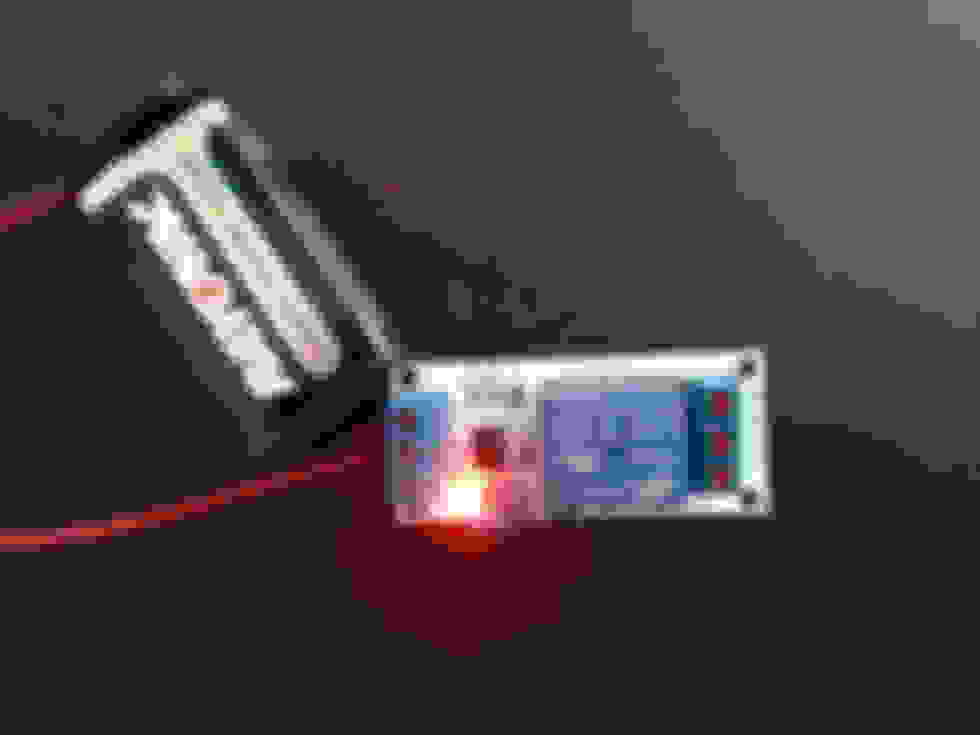
- Take a 9V battery, and connect the positive terminal to the IN1 input of the relay
- Connect the negative terminal to the GND input of the relay
- Note that the relay has jumpers which give you the option of using high current or low current. I believe my jumpers were set for high current.
- At this point, your LED should light up, but the relay isn’t actually “working" yet
- You will need to “short VCC to IN1.” Take a small piece of wire and connect one end to the input labeled VCC and the other end to the input labeled IN1 (this input will also be connected to the positive wire from the 9V battery)
- Now you should hear an audible “CLICK” when power is supplied/removed. The “power side” of your relay is working.
- If you want, you can test this setup in your car with the video feed control circuit.
- We’ll set up the circuit as “NORMALLY CLOSED”
- that is, when there is no power going to the relay, the circuit is closed, and the GPS screen is displayed
- when power is supplied to the relay, the circuit is opened, and the front camera is displayed
- using the photo above, we're going to connect the wires of the video feed control circuit to terminals A and B
- This is easier to show than explain, so here’s a picture of how the relay should be wired when everything is all said and done:

- Now, that you have an understanding of how it works, let’s jump in to the actual installation
d. Installing the relay- In my DBS, to get to the parking switch, we have to remove the front fascia. To do that, we have to remove the shifter panel and shifter. To do that, we have to remove the armrest. To do that, we have to loosen up up the rear ski slope. To do that, well, we basically have to take the whole back interior apart, just as we did earlier when we needed to access the subwoofer. So, I’ll assume that you haven’t put everything in the rear back together yet, and that you already have the ski slope removed.
- Remove the armrest
- There’s a stiff rectangular leather piece toward the back of the armrest that you’ll have to pry off. Your wide trim removal tool works great for this.
- Undo the two screws underneath.
- Remove the cupholder liner.
- Undo the two screws underneath that.
- Note: pay attention to the backing plate under the armrest that these screws attach to. This is a pain to put back together. It took me maybe 45 minutes to reinstall this.
- Carefully lift the armrest up and undo the 3 connectors
- cigarette lighter
- USB
- iPod integration
- Carefully take the armrest out and set it aside
- Remove the center console shifter panel and shifter
- Undo the two screws
- Slide the panel back
- Lift up the panel slightly and disconnect the (five?) electrical connectors
- Put the shifter in neutral, push down on the ****, and turn it counterclockwise about 90 degrees
- Lift up the center console and shifter, and carefully set these aside
- You should have something that looks like this:

- Remove the veneer bezel for the instrument panel. (This is the top part of the fascia that goes over the navigation screen, center AC vents, etc.)
- This is actually pretty easy as long as you know where the clips are
- There are just 4 clips securing this
- one on the right side toward the bottom of the bezel
- one on the left side toward the bottom of the bezel
- one on the right side toward the top of the bezel
- one on the left side toward the top of the bezel
- Use your wide trim tool, and start on one of the sides to disconnect one of the bottom clips
- It should pop off with a little force
- As always, be careful with the leather trim
- When it’s unclipped, work on the clip on the opposite side
- I found it’s better to keep the first trim tool wedged under the bezel, while using a second trim tool to unclip the other side. This prevents the bezel from dropping down and clipping back into place.
- When the bottom portion is unclipped, undo the top clips
- Disconnect any connectors
- These connectors are “notched” and only fit a specific way, so you don’t have to worry about remembering which connector goes where
- Carefully remove the top bezel and set it aside.
- Remove the Center Stack Assembly (That’s the Aston Martin name for it. This is basically the panel with all your radio, AC, ***** and switches)
- Two screws at the bottom
- Two screws at the top
- Gently pry this panel out
- Disconnect a bunch of connectors
- Note: I was able to get all but one of the connectors disconnected, so I had to do the following with the Center Stack Assembly still partially connected. It was a pain but doable, and it required a bit of extra care to make sure I didn’t scratch anything
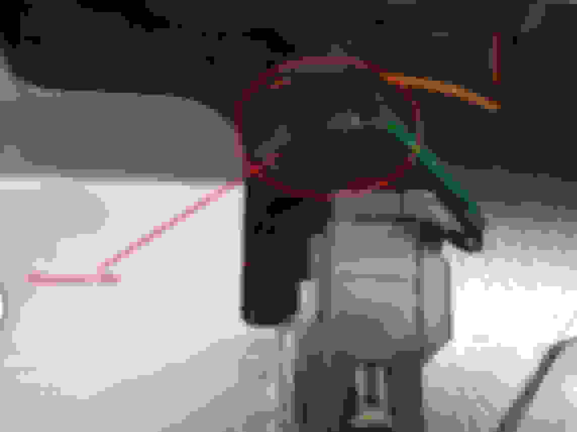
- Find the connector that goes to your parking switch
- Our goal here is to find the power/ground wires that we’re going to connect to the “power side” of the relay
- Here's mine:

- For the life of me, I couldn’t read the AM circuit diagrams, so what I did was remove the parking switch (not pictured) and connect the terminals of a 9V battery at random to the leads within the switch until I figured out which ones cause the LED on the switch to light up.
- I determined that the green wire and one of the black/pink wires were power and ground for the LED. Looking at the picture from left-to-right, these would be wires #2 and #3.
- I can’t specify which one is power and which one is ground, because I didn’t verify my hypothesis until after everything was soldered and all the panels were put back together, and by that time my two wires were mixed up, and I couldn’t be sure. But that’s not that big a deal.
- Tap into the power and ground wires of the parking switch LED
- Okay, you’ll need two lengths of wire (maybe 4’ each). These will be go from the power/ground wires of the parking switch LED and into the fusebox (where we will house the relay)
- Remove some of the insulation for the green wire. Solder one end of one of your wires to it. Wrap this connection up. (I couldn’t find a way to seal this connection with shrink tubing, so I settled for wrapping it with electrical tape.)
- Do the same with the black/pink wire.
- Take these these wires, fish them through the interior of the panel down toward the fusebox.
- Connect the power wires from the parking switch LED to the "power side" of the relay
- By now, you should know where these go, since you already did this step when testing the relay out with the 9V
- Route the wires from the video feed control circuit to the relay in the fusebox
- Use the same path you used for the VBB4 power lines and the video camera RCA cable
- You’ll probably need to solder extensions to the switch wires
- Connect these wires to the relay as a NORMALLY CLOSED circuit
- Optional: Use some type of an enclosure to cover the relay.
- I bought an enclosure for my relay off eBay, but it didn’t fit perfectly, so I’m not going to recommend this one:

- I bought an enclosure for my relay off eBay, but it didn’t fit perfectly, so I’m not going to recommend this one:
- Secure the relay with Velcro or something
- Put your car back together


Congratulations! That's it. Soooo easy.
Last edited by wysoseereeus; Jul 13, 2015 at 01:21 PM.

Registered User
Joined: Oct 2007
Posts: 532
From: Ohio
Rep Power: 40
cool write up, what year vehicle? That is a lot of work, the link I gave you they said an hour for a rear camera install and it is done at the screen.
On a professional note, as i have done many electronics installs in high end vehicles, if the factory doesn't use posi-taps for its wiring I wouldn't either. Also Pyle is flea market quality with low quality resolution. Personally I would look at the Alpine cameras, for 1, properly installed you would get a better view behind the vehicle. and more control of your cameras, including people/obstacle/and animal detection. especially since the vehicle isn't a 03 Monte Carlo.
Not saying your way is wrong, but I believe the guys locally here have it down to a science, especially if they are knocking them out in an hour and warrantying it for 3 years. But they are doing it from model year 2011 and up.
also when I called them they were looking for an AM to make a plug and play remote start kit, they said free for the vehicle but you had to supply them with 3 keys... that could get pricey.

Registered User

Joined: Aug 2007
Posts: 2,699
From: MD
Rep Power: 173

This is a really great DIY write up!. I would love to see it placed into the FAQ and even highlighted as a model example for those to follow when doing their own DIY. It's a continuous knowledge share like this that makes the enthusiast community so rich. People build their know how on the backs of others like this and we all learn along the way. Thanks for this nice effort.
Last edited by deckman; Jul 3, 2015 at 06:38 AM.


Registered User
Joined: May 2013
Posts: 431
From: Glendale, CA
Rep Power: 36
Trending Topics

Registered User
Joined: Aug 2014
Posts: 324
From: USA
Rep Power: 35
Slight thread hijack...
First, of all, I'm adding my own "We Are Not Worthy!" kudos. Great work!
Second, I'm intrigued by the concept of daisy-chaining into the nav system.
I have a 2006 DB9, and as the nav has audio that runs through the main cabin stereo system, I'm wondering if there's any potential to daisy-chain an auxiliary audio input through the nav "plumbing" (early cars don't have an aux in).
Any thoughts?
Thread Starter
|
Registered User
Joined: Mar 2015
Posts: 86
Rep Power: 18
First, of all, I'm adding my own "We Are Not Worthy!" kudos. Great work!
Second, I'm intrigued by the concept of daisy-chaining into the nav system.
I have a 2006 DB9, and as the nav has audio that runs through the main cabin stereo system, I'm wondering if there's any potential to daisy-chain an auxiliary audio input through the nav "plumbing" (early cars don't have an aux in).
Any thoughts?
Second, I'm intrigued by the concept of daisy-chaining into the nav system.
I have a 2006 DB9, and as the nav has audio that runs through the main cabin stereo system, I'm wondering if there's any potential to daisy-chain an auxiliary audio input through the nav "plumbing" (early cars don't have an aux in).
Any thoughts?
You might want to try reaching out to Bob at VolvoTech.eu (or another interface supplier) to see if he sells or can recommend a unit that will do the job.
Also, seems some people have had success with the Denison unit. (I've never used it, so I can't comment on it personally.)
Thread Starter
|
Registered User
Joined: Mar 2015
Posts: 86
Rep Power: 18
Thanks for all the compliments and the great feedback, everyone! This forum has been an invaluable resource to me, and I owe a lot to everyone who's taken the time to share their knowledge, suggestions, and insights. Just trying to do what I can to give a little back.
Registered User
Joined: Oct 2007
Posts: 532
From: Ohio
Rep Power: 40
Audio Integration:
For the newer vehicles (06+) with the Volvo Alpine optical amplifier, NAVTV has a MOST AUX unit that can be put inline on the optical, now i know you guys are going to yell bloody murder, but you manually have to turn it on and off
If you forget to turn it off it will have a hard time booting up and you will need to cycle the ignition. the way I got around this on the BMW, was to add a hidden micro stealth push button that would activate a PAC TR7 that would turn the optical piece on, it would default to the normal optical setting when the vehicle was turn off so the next time you started the vehicle the audio gateway would boot up correctly.
Here is the link https://navtv.com/products/NTV-KIT14...aux-aston.html for questions, my go to person is derek@navtv.com very smart!