
DIY X51 intake manifold on 987 3.4 installation

Thread Starter
|
Registered User
Joined: Oct 2007
Posts: 292
From: MD
Rep Power: 42


DIY X51 intake manifold on 987 3.4 installation
*this article has many pictures you may need to refresh your browser for all of them to appear*
difficulty 1-10: 10
Hp increase: 8-12WHP...so far
installation time: 10-20HRS (approximate)
*reasonable knowledge required
tools needed:
socket wrench set /metric
several extensions
torx wrench bits
universal joints
flathead screwdriver
phillipshead screwdriver
metal files
channel lock pliers
magnetic pen (pick up tool)
*8mm ratcheting wrench
heat gun
strutking engine cover
Custom X51 Software (Scott Slauson from PCA made mine)
This was a pretty big project, first time its been done on a 3.4. that I know of, I want to thank Scott from PCA for the assistance in making this project possible.
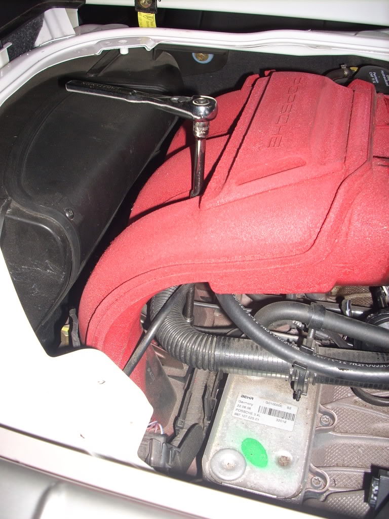
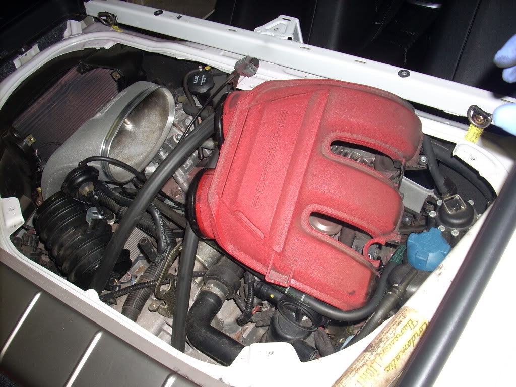
first of all start by removing your engine cover.

also remove the front engine cover
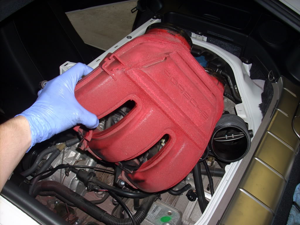
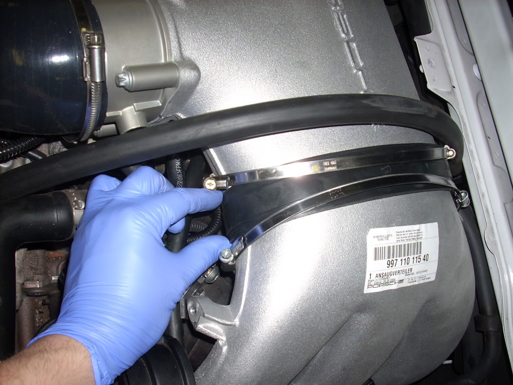
once the engine cover is off remove the plenum and distribution tubes (with flap) there are a total of 10 straps to remove.


dont forget the one on the MAF
remove the plenum hose, dont worry seeing oil is normal

remove the plastic clips from the plenum by squeezing them on the rings, unclip the electrical TB wire

flip up the plenum and pull out the oil return hose.

now remove the plenum

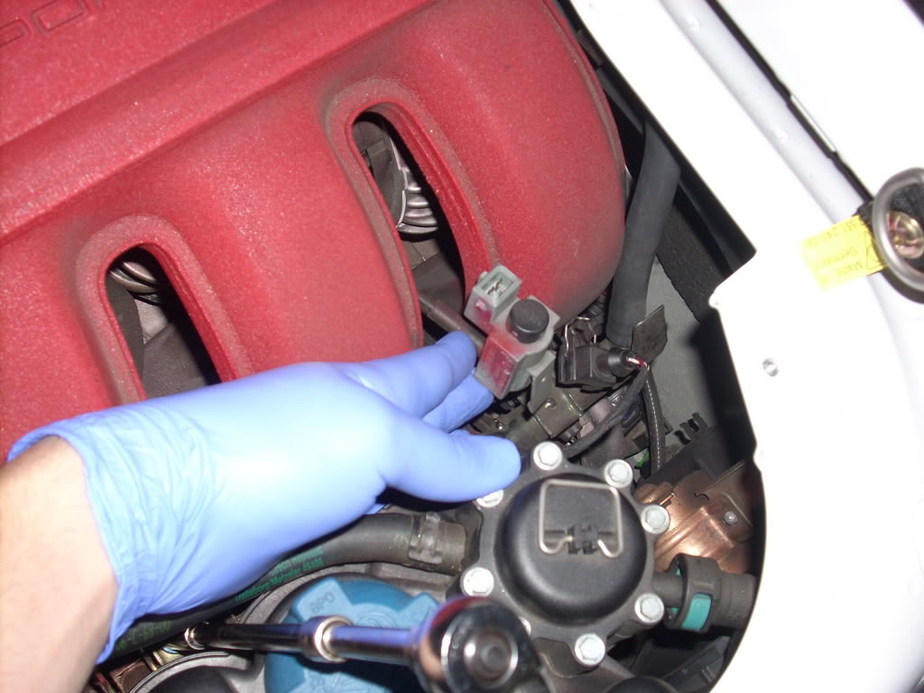
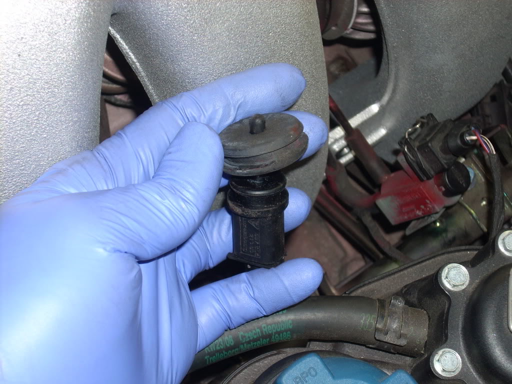
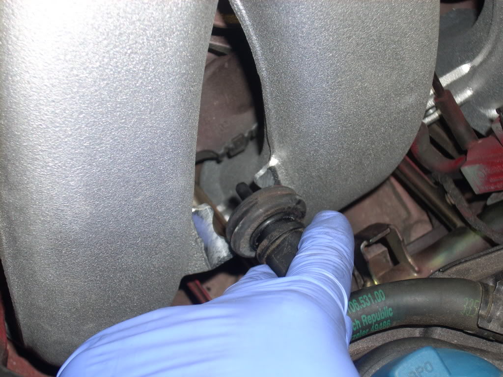
pull up the vacuum sensor from the intake manifold,there are two of these, one on each side, they have electrical harness clips on top
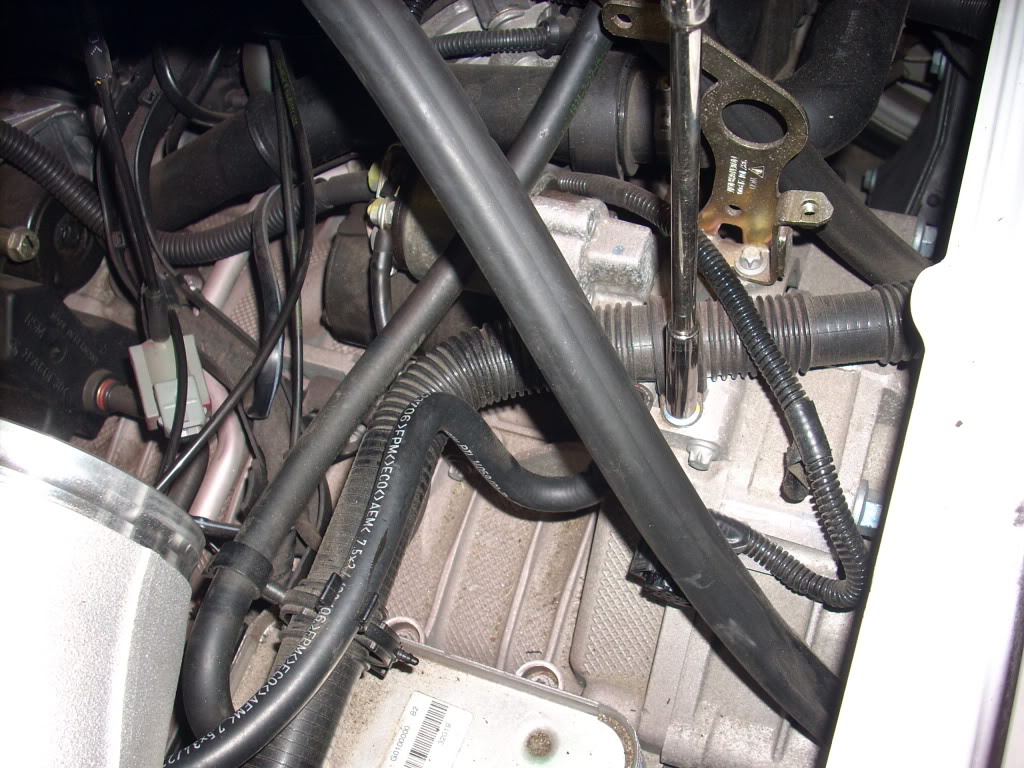
Remove the distribution tube with the internal flap, cut the vacuum line and plug it, you should have a total of two vacuum lines plugged now, I used a screw and a zip tie on one of them, the other has the IPD kit hardware
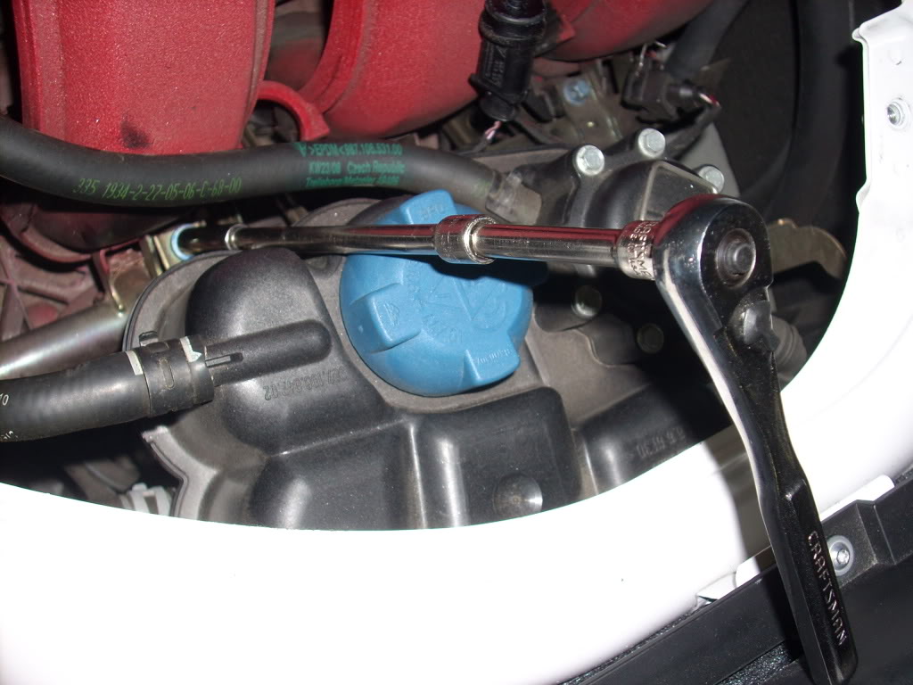
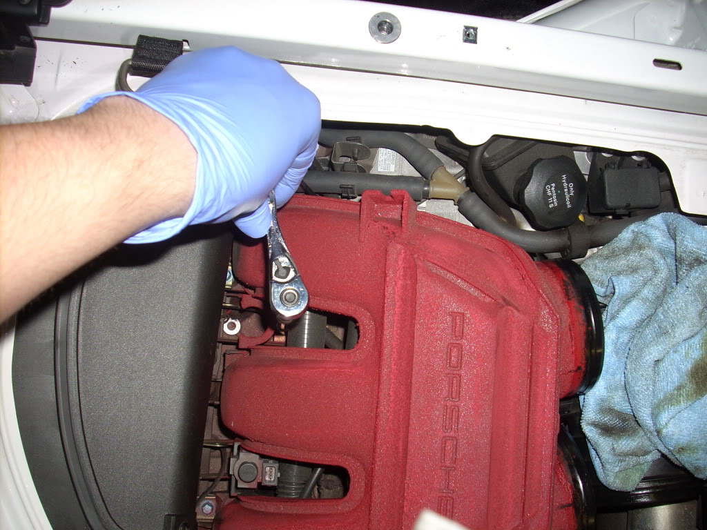
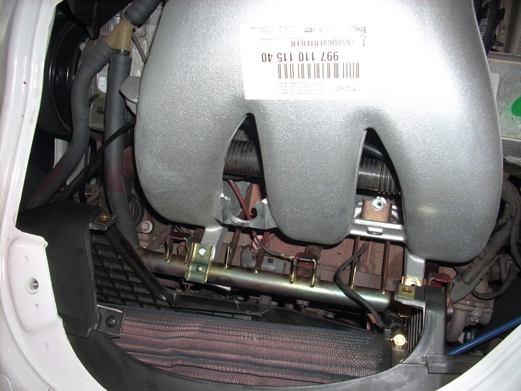
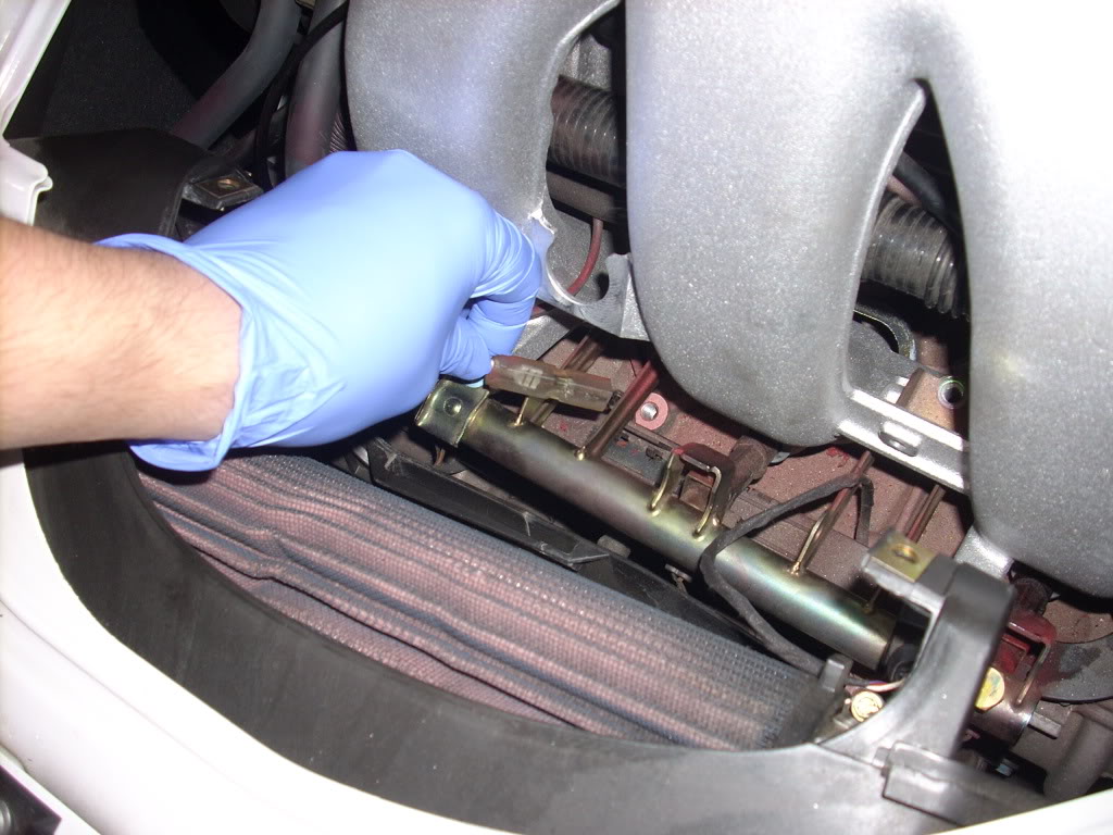
remove the fuel rail bolts 8mm, there are two on each side, use an extension here
remove the intake cover on the other side to gain access to the other screws
there is an electrical clip that needs to be removed, use a flat head screw driver to pry it out of the clip
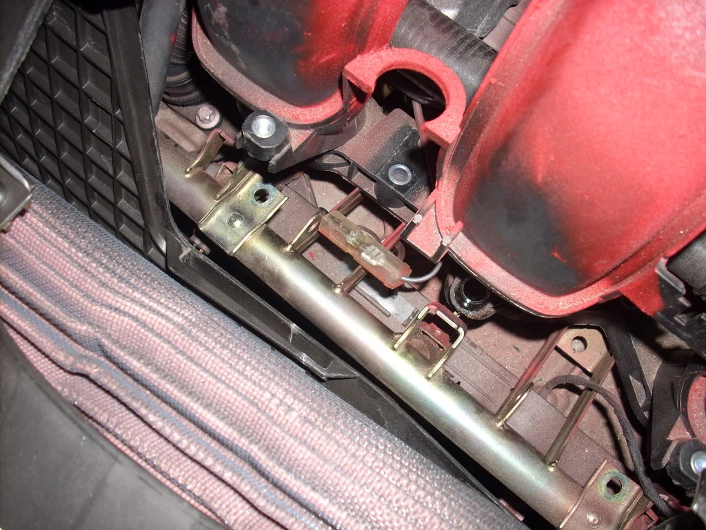
now simply pull it apart
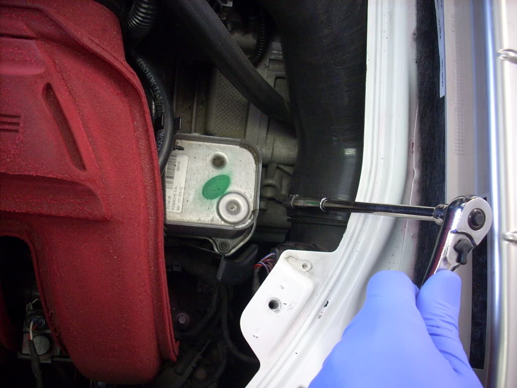
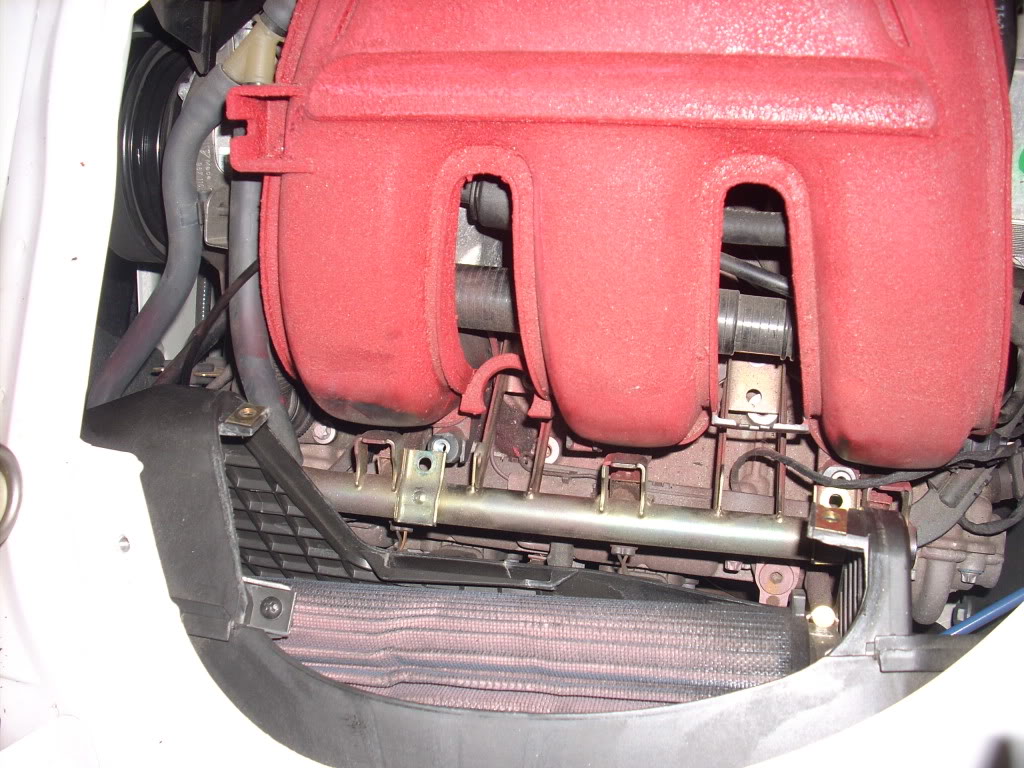
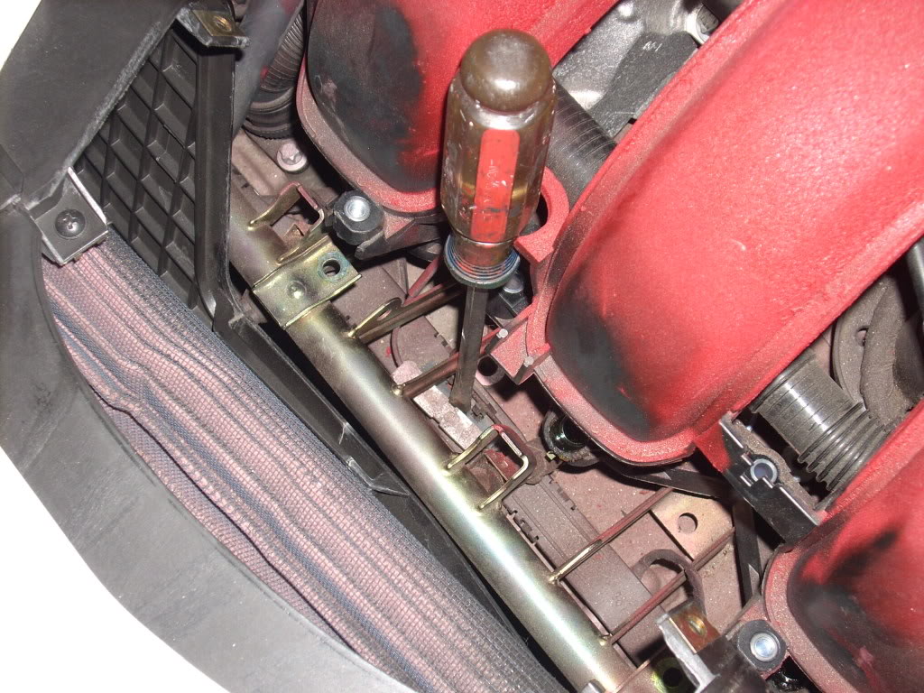
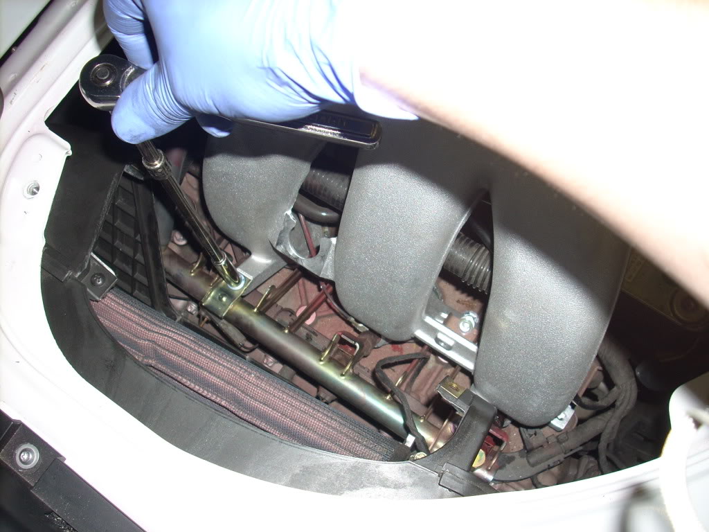
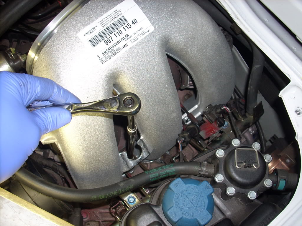
now start to remove the intake manifold screws, there are 4 total on each side, you will need an extension for this
1...
2...
3...
difficulty 1-10: 10
Hp increase: 8-12WHP...so far
installation time: 10-20HRS (approximate)
*reasonable knowledge required
tools needed:
socket wrench set /metric
several extensions
torx wrench bits
universal joints
flathead screwdriver
phillipshead screwdriver
metal files
channel lock pliers
magnetic pen (pick up tool)
*8mm ratcheting wrench
heat gun
strutking engine cover
Custom X51 Software (Scott Slauson from PCA made mine)
This was a pretty big project, first time its been done on a 3.4. that I know of, I want to thank Scott from PCA for the assistance in making this project possible.
first of all start by removing your engine cover.
also remove the front engine cover
once the engine cover is off remove the plenum and distribution tubes (with flap) there are a total of 10 straps to remove.
dont forget the one on the MAF
remove the plenum hose, dont worry seeing oil is normal
remove the plastic clips from the plenum by squeezing them on the rings, unclip the electrical TB wire
flip up the plenum and pull out the oil return hose.
now remove the plenum
pull up the vacuum sensor from the intake manifold,there are two of these, one on each side, they have electrical harness clips on top
Remove the distribution tube with the internal flap, cut the vacuum line and plug it, you should have a total of two vacuum lines plugged now, I used a screw and a zip tie on one of them, the other has the IPD kit hardware
remove the fuel rail bolts 8mm, there are two on each side, use an extension here
remove the intake cover on the other side to gain access to the other screws
there is an electrical clip that needs to be removed, use a flat head screw driver to pry it out of the clip
now simply pull it apart
now start to remove the intake manifold screws, there are 4 total on each side, you will need an extension for this
1...
2...
3...
Last edited by porsched4ed; Apr 27, 2009 at 07:35 AM.
Thread Starter
|
Registered User
Joined: Oct 2007
Posts: 292
From: MD
Rep Power: 42
X51 install part 2
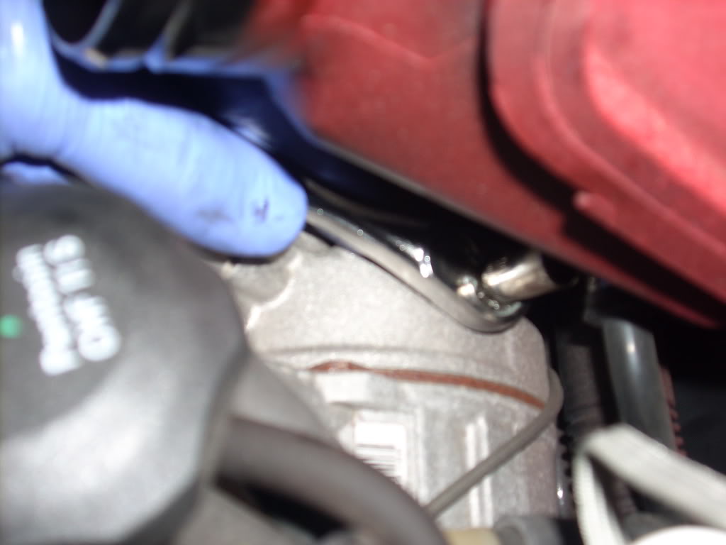
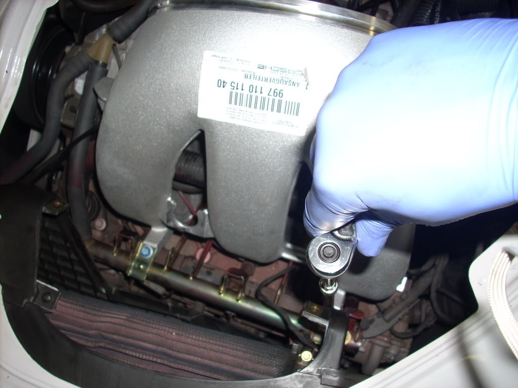
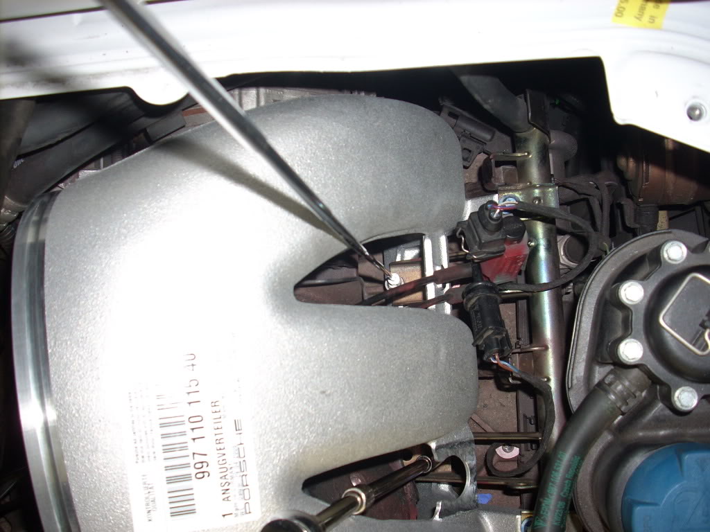
and 4, which is tricky, thats why you need the engine cover off to see it from behind the drivers seat....
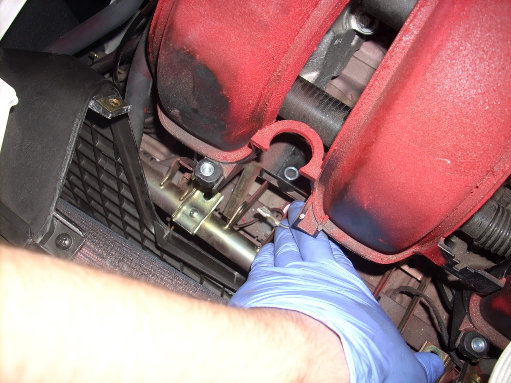
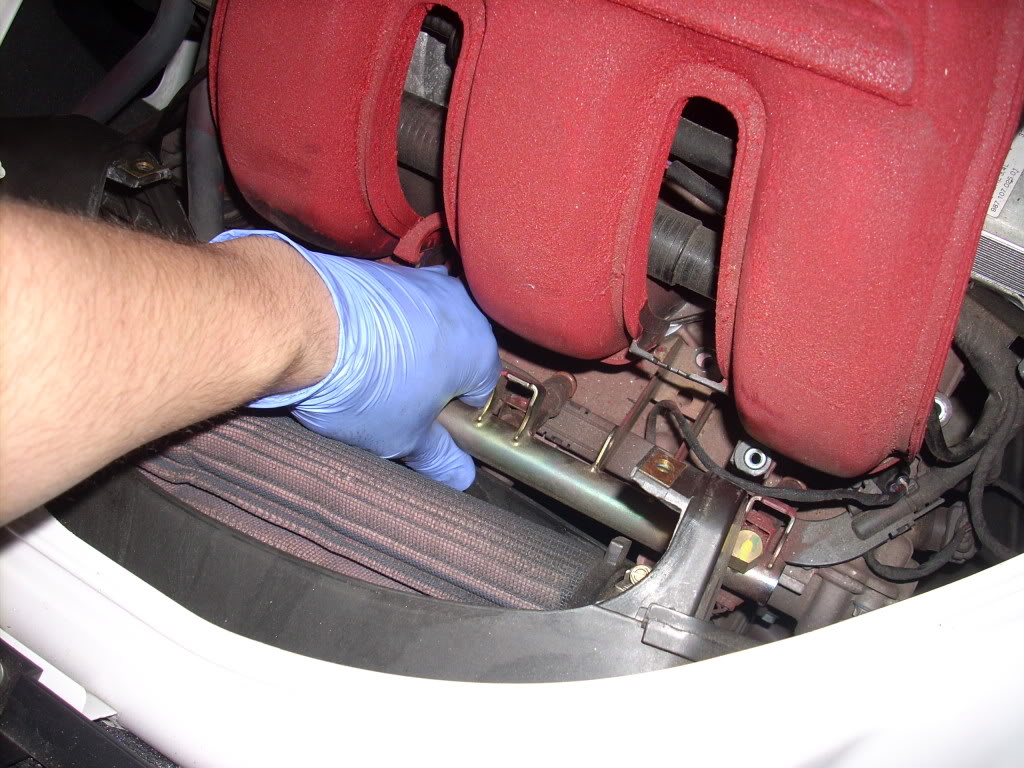
now pull up the fuel rail
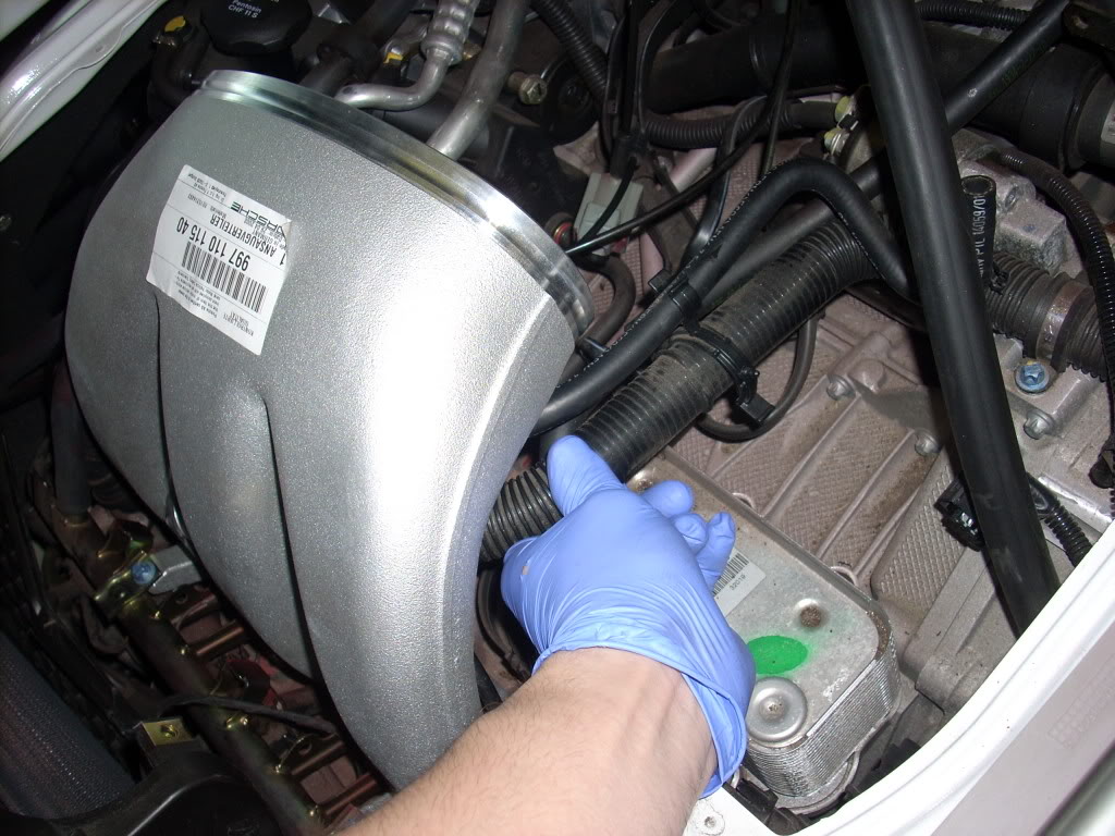
turn the top of the manifold towards you leaving the base in contact with the engine
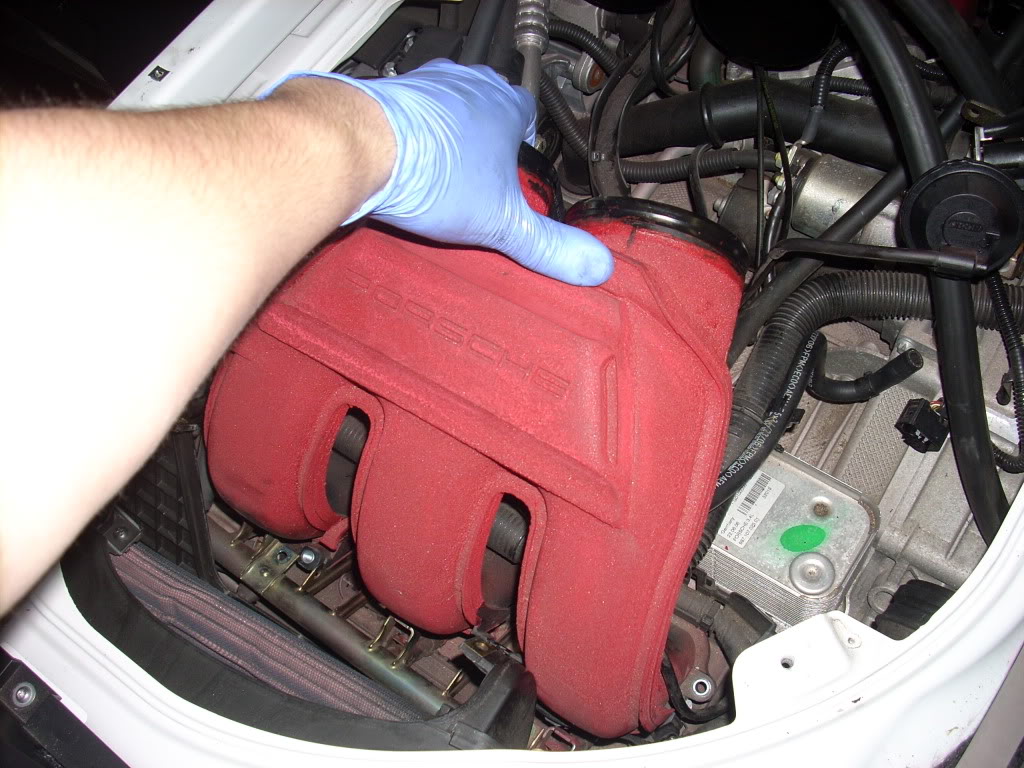
lift the manifold and slide the fuel rail under the manifold, be careful not to pinch the injector seals, there is a bolt under the drivers side manifold that you can get to by tilting it up
sorry for the blurry pic, you cant pull it out until this is off
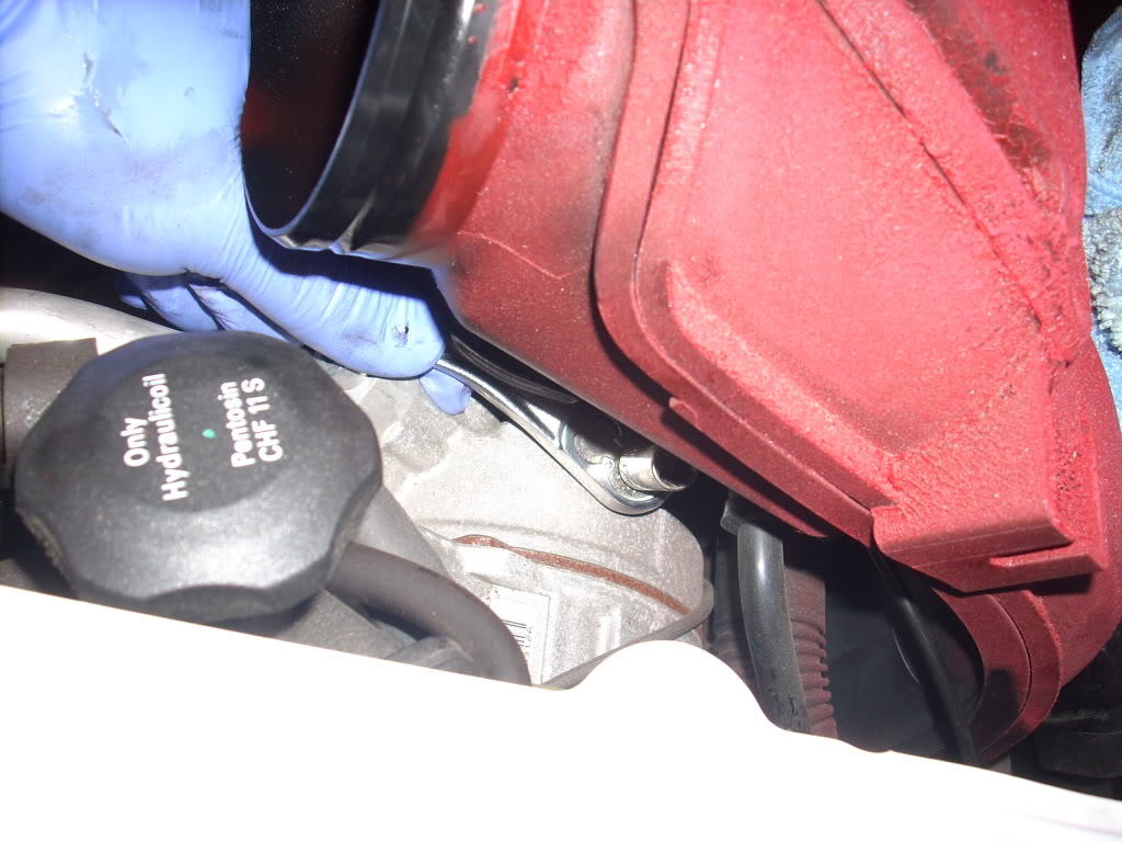
here I tackled it from the other side, which was easier
once that is off you are free, so pull it out
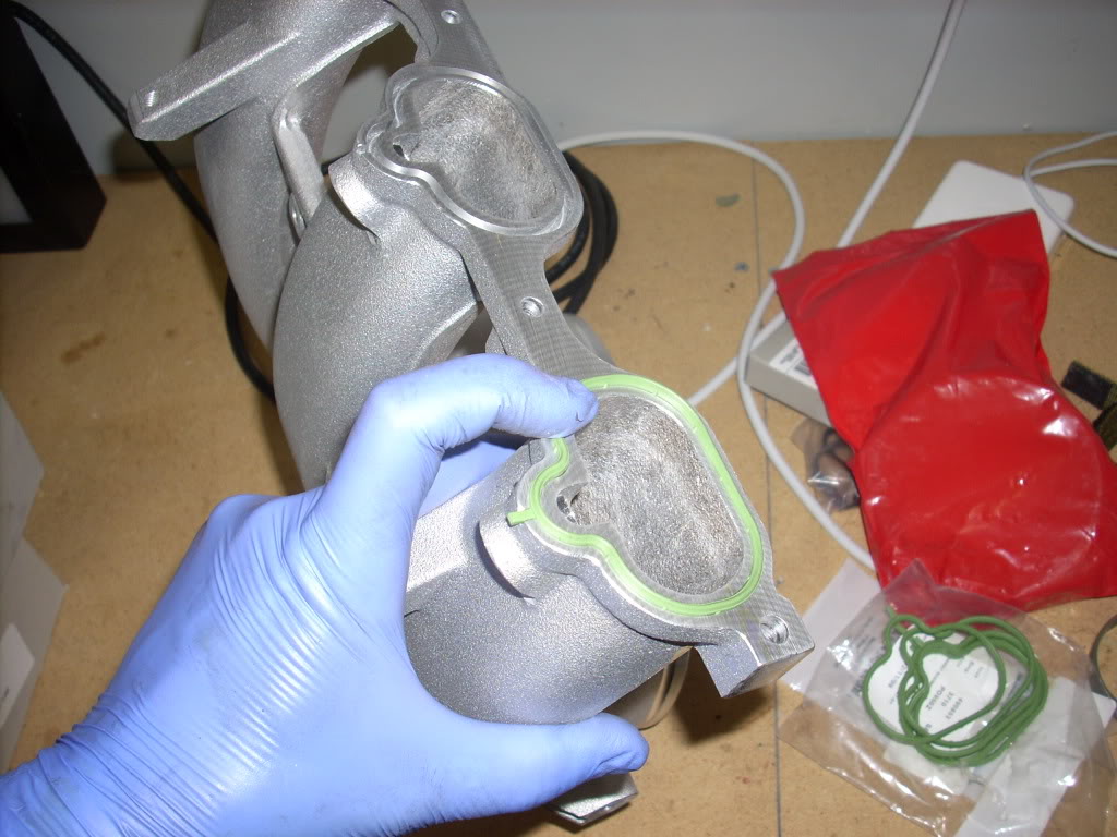
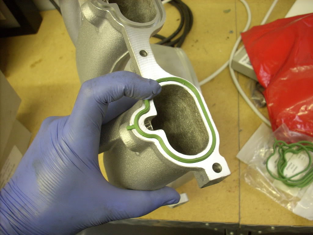
lets get the x51 intake onto the drivers side now, start by putting on the new gaskets, they only fit one way
not this is easier to slide back in because of the shape, run the wire for the alternator through and over the base
pull the fuel rail out and push the intake onto the engine
tighten the screws back on the fuel rail, make sure the injectors line up and they should pop right in
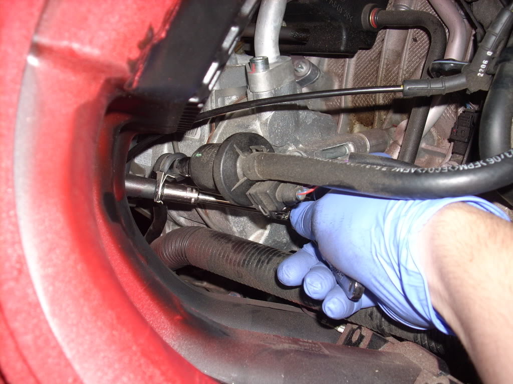
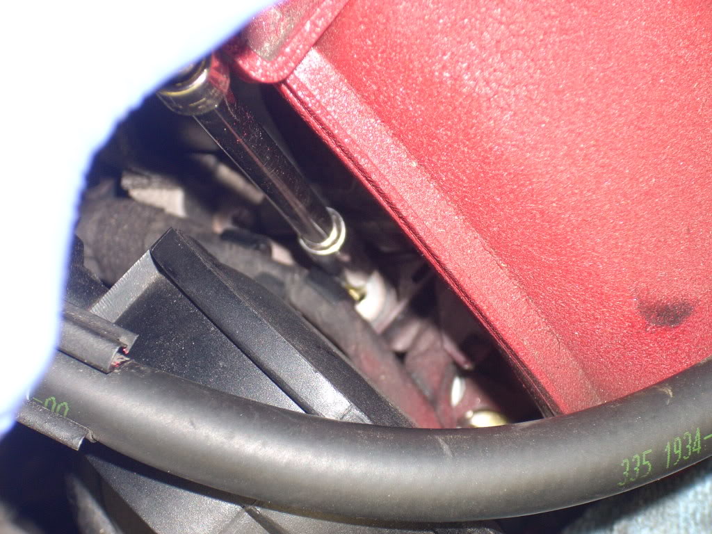
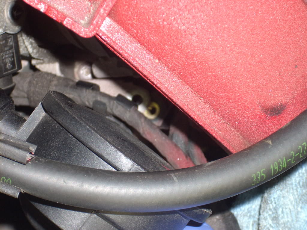
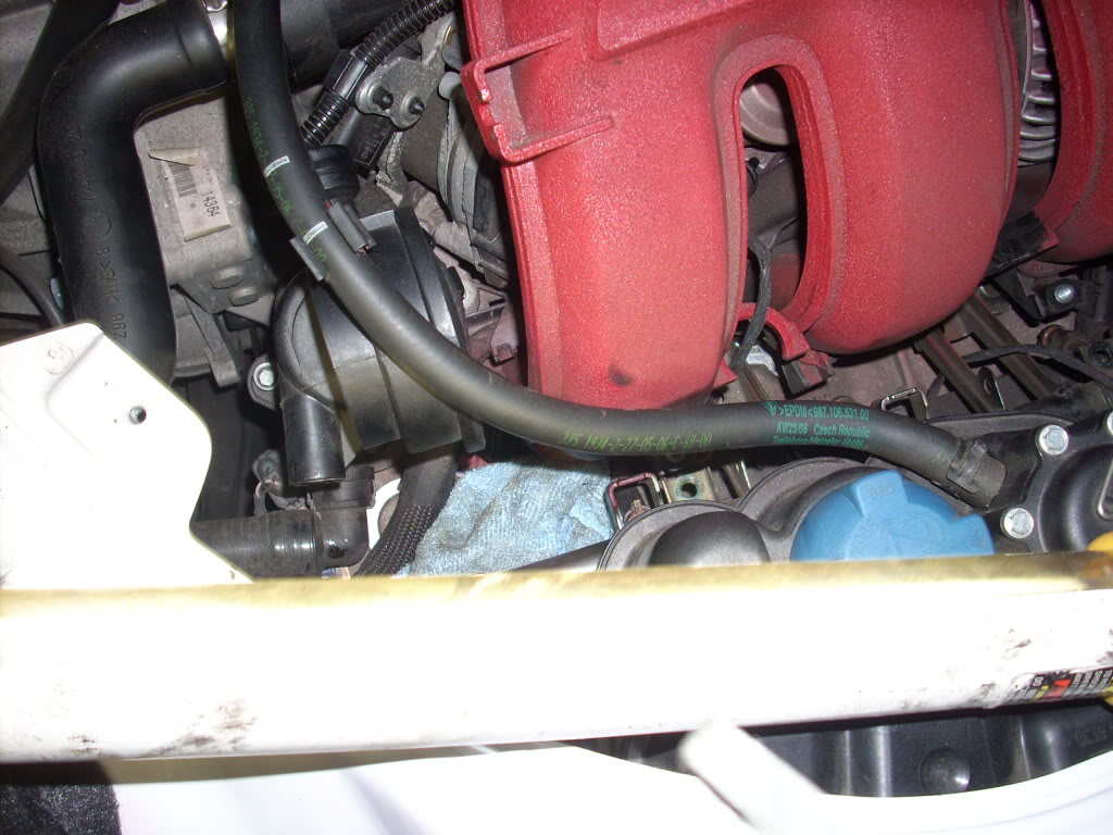
this hose needs to move back a little
remove this screw to give play to the hose it is connected to
now connect the wire for the alternator
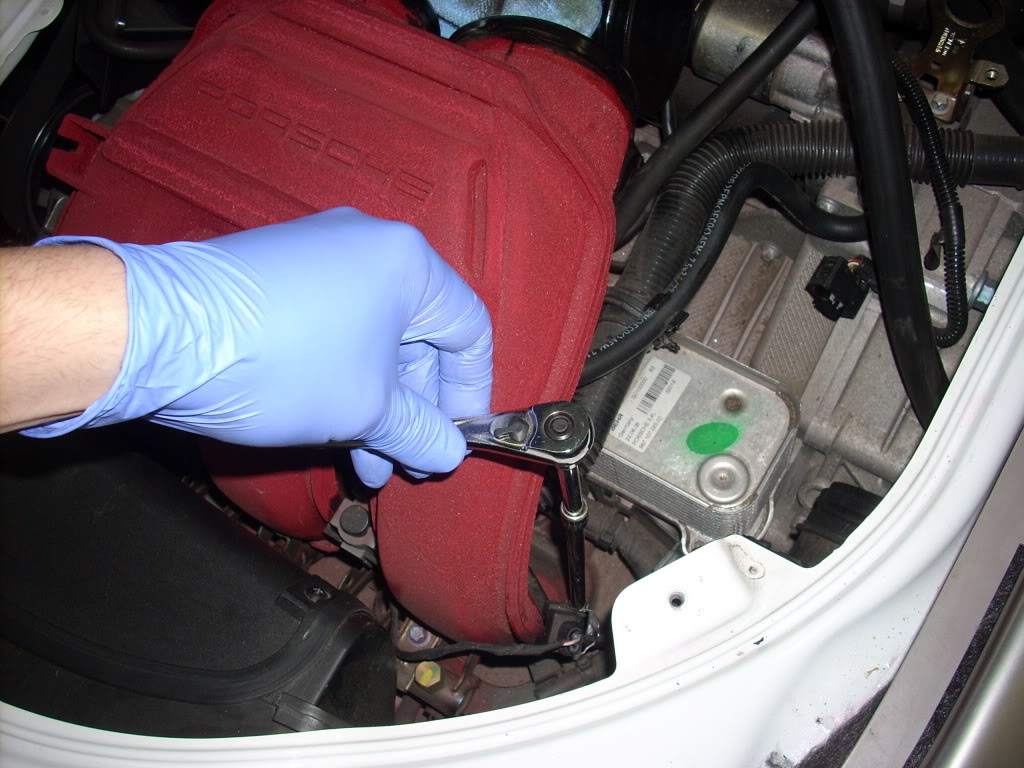
put all of the screws back in, the only one that is difficult is the one closest to the drivers seat, you need a ratcheting 8mm wrench, due to the design of the runners that deliver more air to the engine
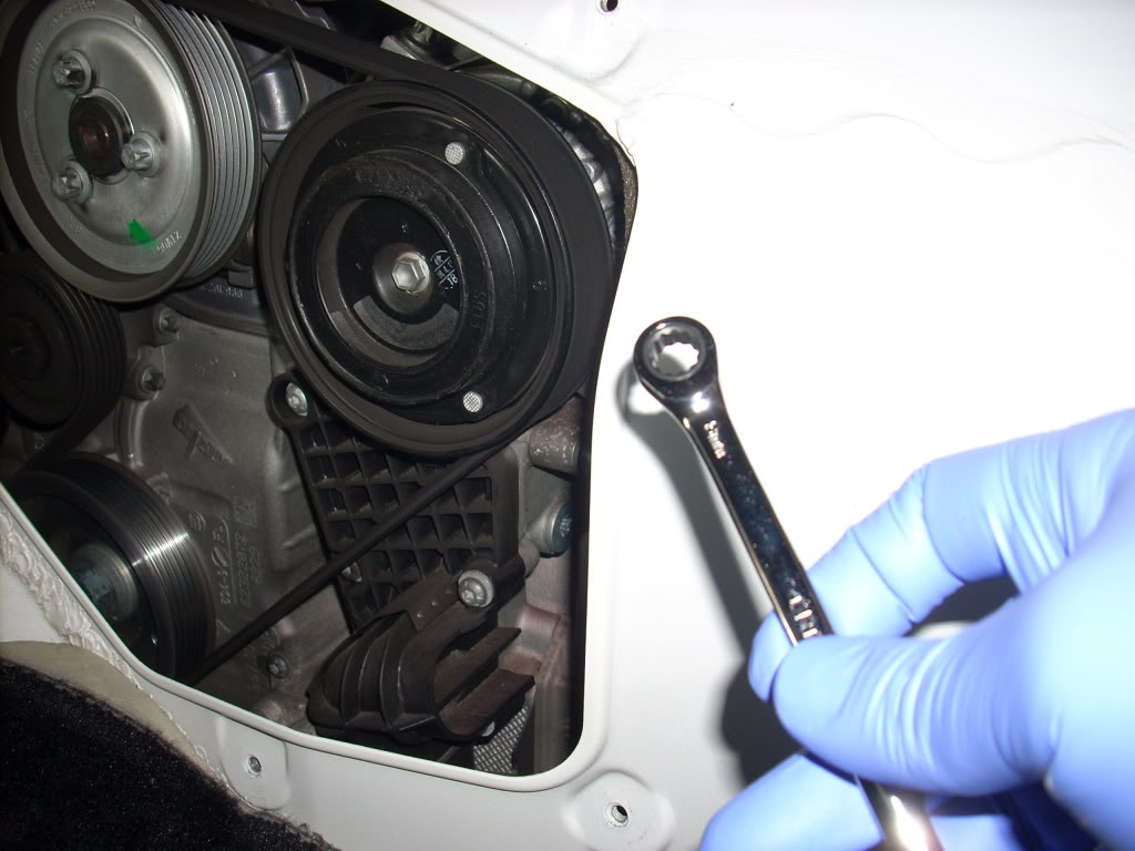
this takes patience...
now pull up the fuel rail
turn the top of the manifold towards you leaving the base in contact with the engine
lift the manifold and slide the fuel rail under the manifold, be careful not to pinch the injector seals, there is a bolt under the drivers side manifold that you can get to by tilting it up
sorry for the blurry pic, you cant pull it out until this is off
here I tackled it from the other side, which was easier
once that is off you are free, so pull it out
lets get the x51 intake onto the drivers side now, start by putting on the new gaskets, they only fit one way
not this is easier to slide back in because of the shape, run the wire for the alternator through and over the base
pull the fuel rail out and push the intake onto the engine
tighten the screws back on the fuel rail, make sure the injectors line up and they should pop right in
this hose needs to move back a little
remove this screw to give play to the hose it is connected to
now connect the wire for the alternator
put all of the screws back in, the only one that is difficult is the one closest to the drivers seat, you need a ratcheting 8mm wrench, due to the design of the runners that deliver more air to the engine
this takes patience...
Thread Starter
|
Registered User
Joined: Oct 2007
Posts: 292
From: MD
Rep Power: 42
X51 install part 3
you have little space to work with...
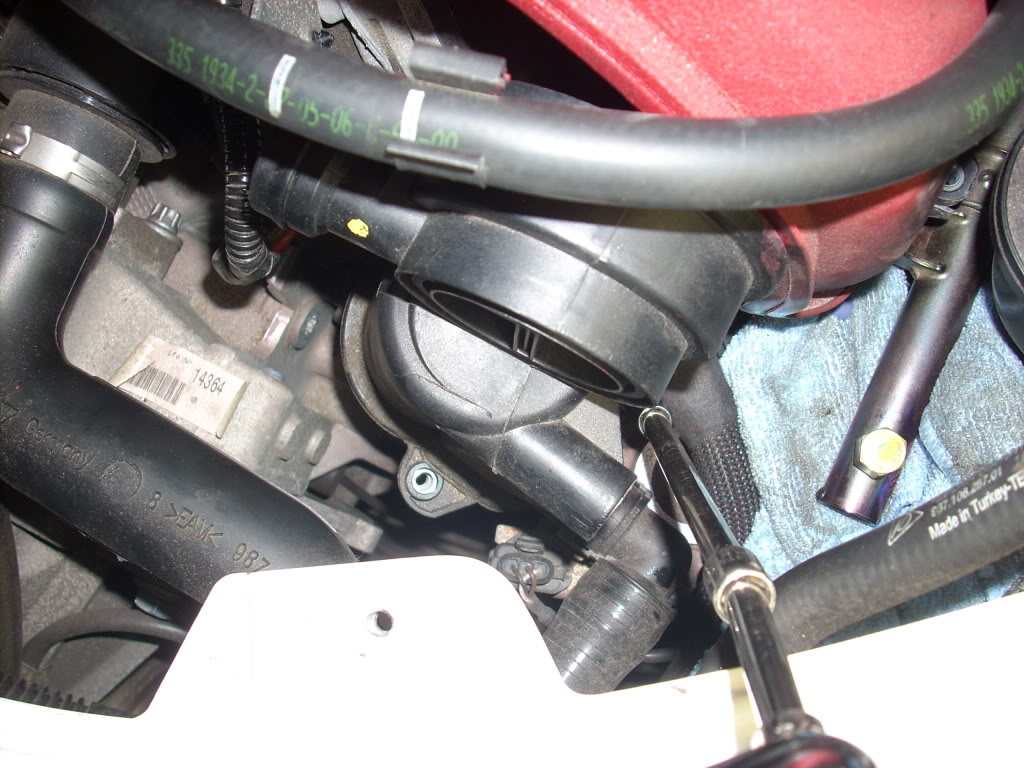
there are some screws you will have to remove on the "oil vacuum, air breather pump?" in order to get to all of the screws for the passengers side
you will have to use a flat head to clip off the electrical wires from the fuel rail, this is done from the engine cover behind the seats
this snaps off
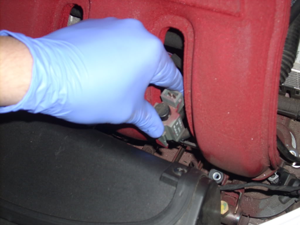
now you will have to remove the electrical harness off the injectors, they are held in place by metal clips. you dont have to remove them completely like I did, but I found it easier, there are 3 of these total
dont loose these, magnetic pen comes in handy here
now you are able to move the fuel rail out of the way
this gives the clearance needed to get the manifold out
getting the manifold out is a little tricky but it will come out with a little wiggling
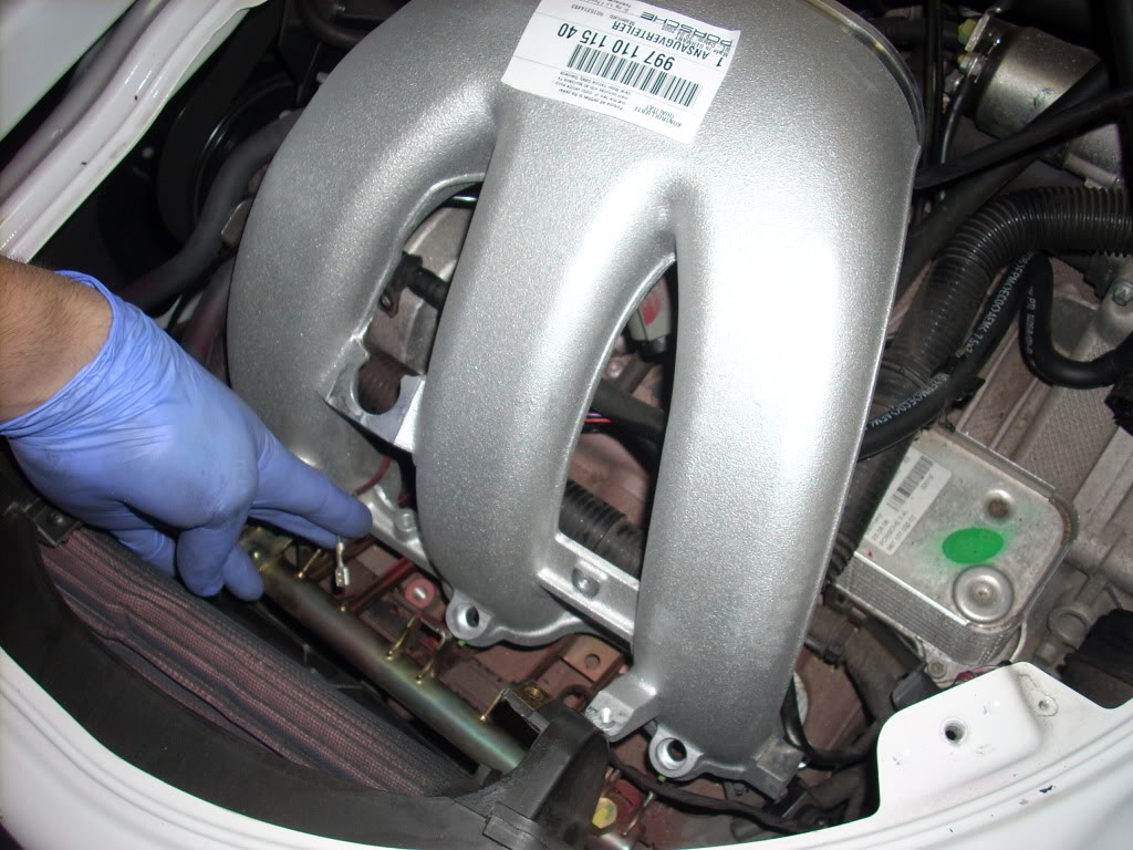
now put the X51 manifold in, use the magnet pen to guide your screws in
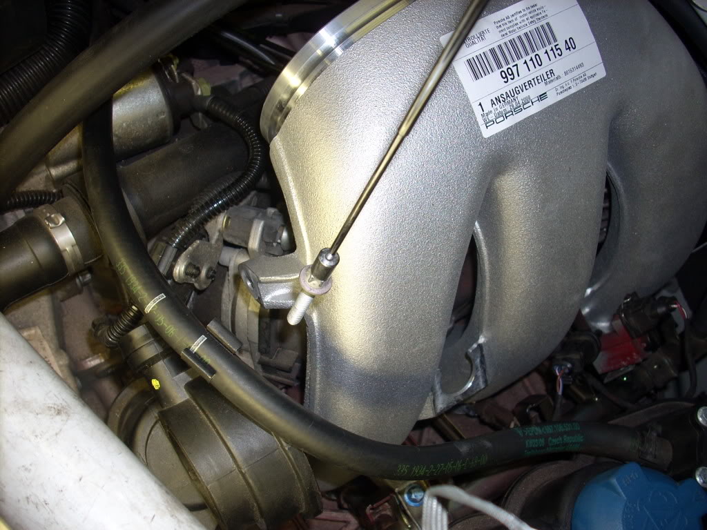
tighten the fuel rail and manifold screws, just like the other side
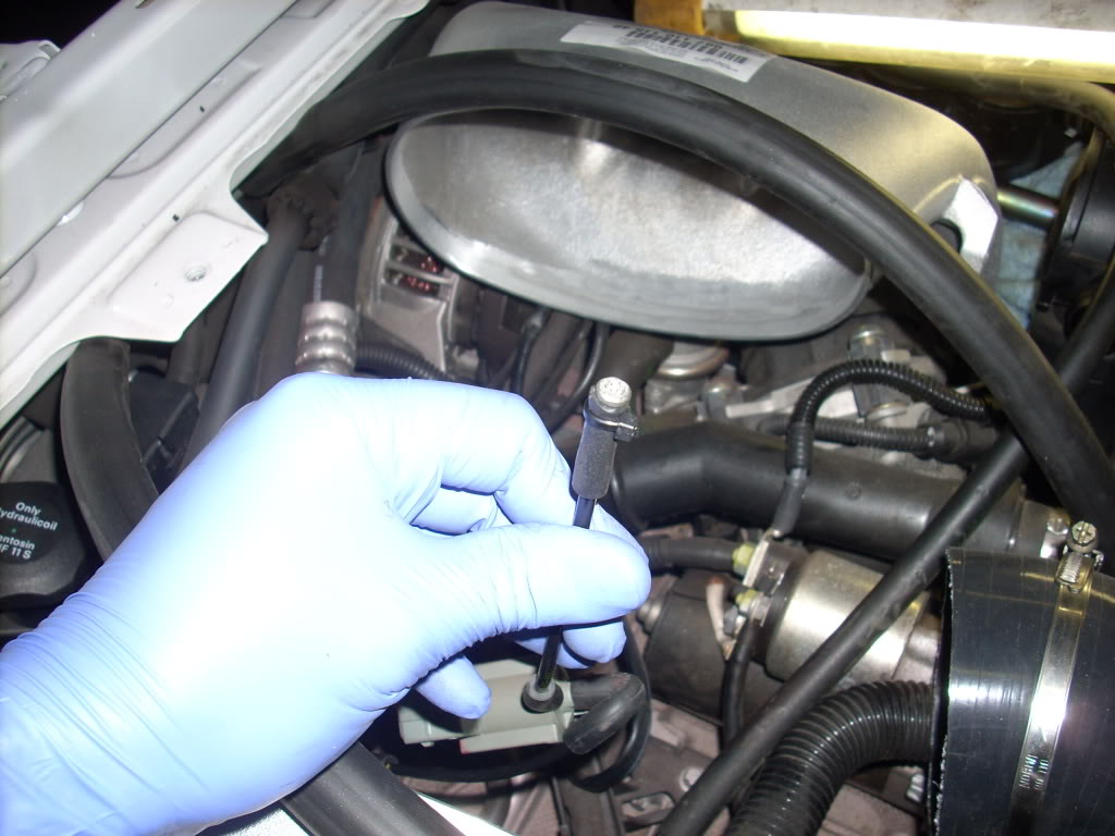
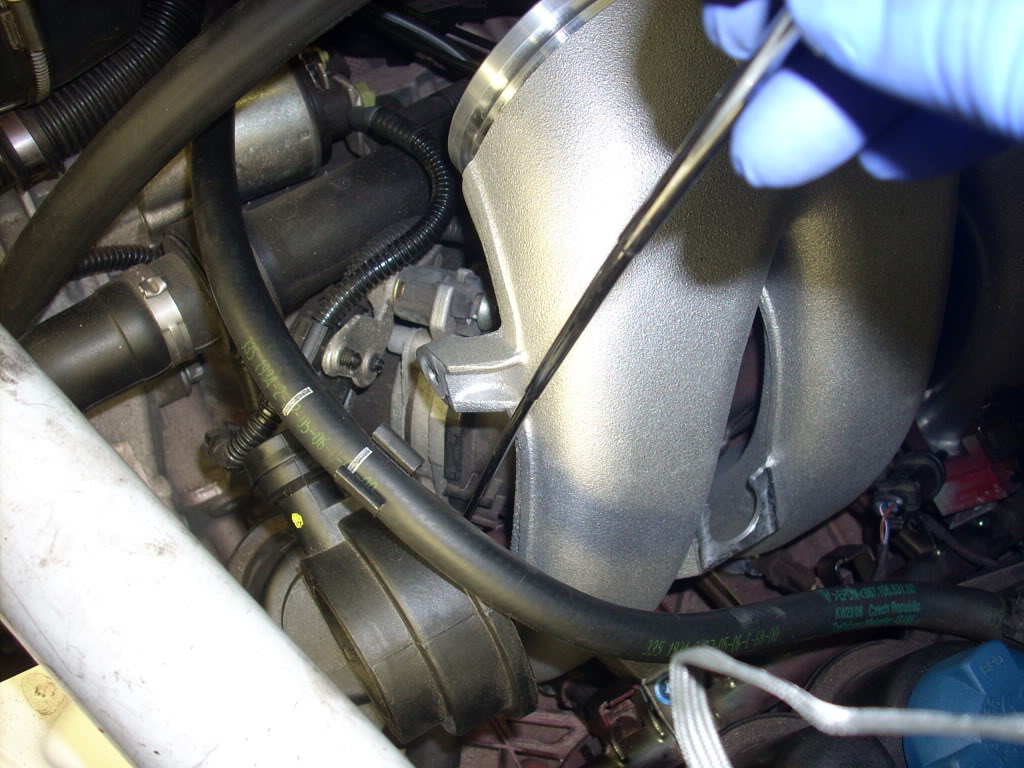
put the temp sensor back in the rubber holder
pop it back onto the manifold
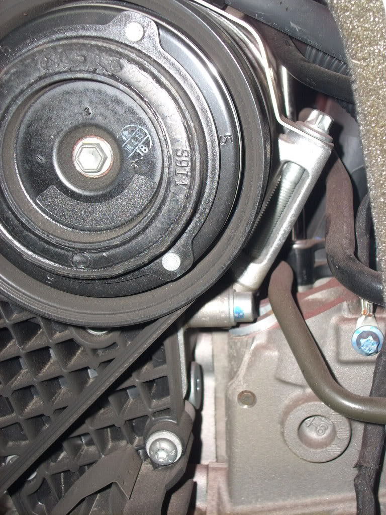
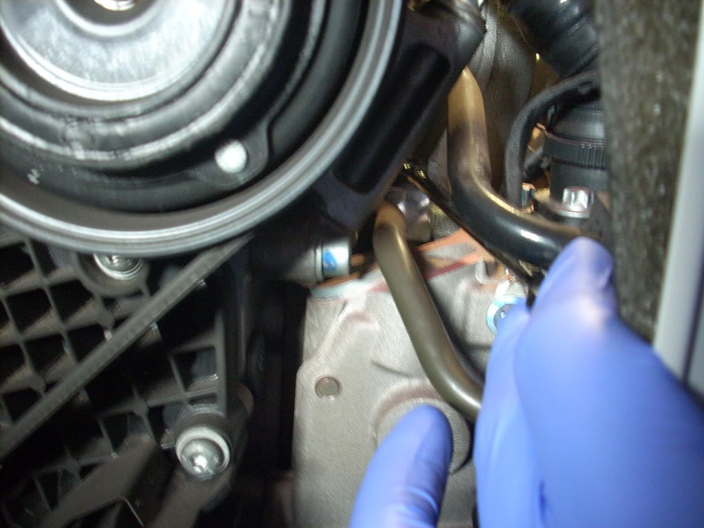
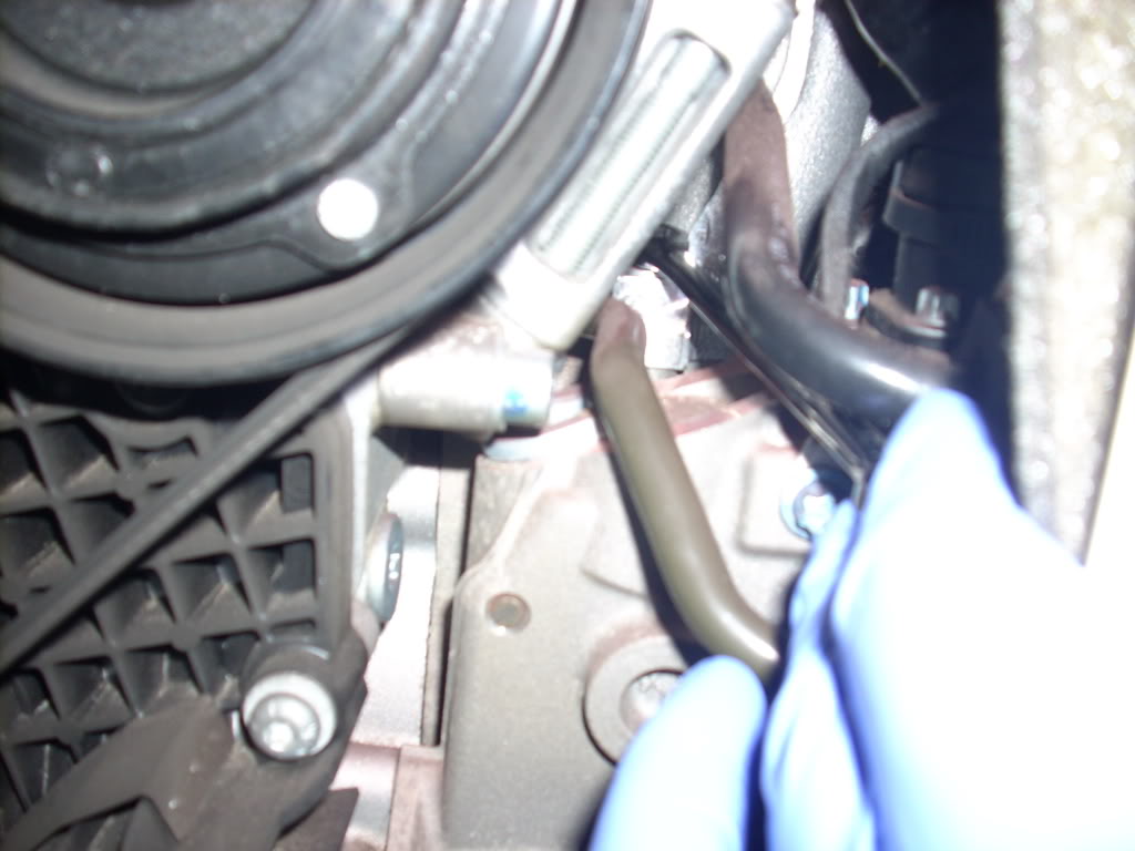
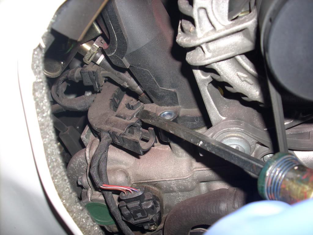
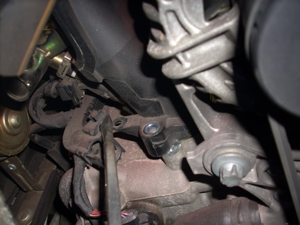
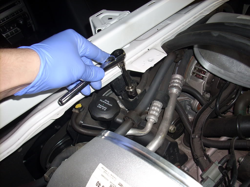
now you need to remove the ground screw to move the trans. lines
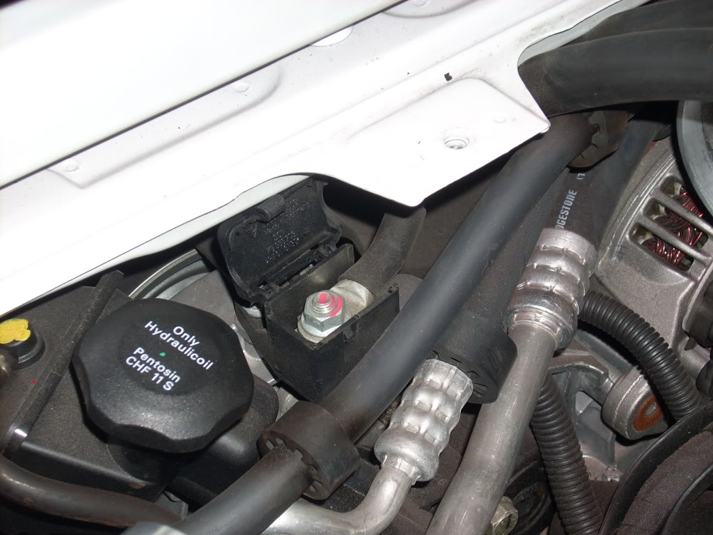
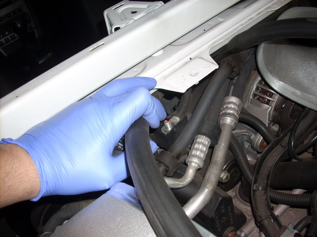
once you've got it off pull the closest line on the other side of the ground post
there are some screws you will have to remove on the "oil vacuum, air breather pump?" in order to get to all of the screws for the passengers side
you will have to use a flat head to clip off the electrical wires from the fuel rail, this is done from the engine cover behind the seats
this snaps off
now you will have to remove the electrical harness off the injectors, they are held in place by metal clips. you dont have to remove them completely like I did, but I found it easier, there are 3 of these total
dont loose these, magnetic pen comes in handy here
now you are able to move the fuel rail out of the way
this gives the clearance needed to get the manifold out
getting the manifold out is a little tricky but it will come out with a little wiggling
now put the X51 manifold in, use the magnet pen to guide your screws in
tighten the fuel rail and manifold screws, just like the other side
put the temp sensor back in the rubber holder
pop it back onto the manifold
now you need to remove the ground screw to move the trans. lines
once you've got it off pull the closest line on the other side of the ground post
Last edited by porsched4ed; Apr 27, 2009 at 07:36 AM.
Thread Starter
|
Registered User
Joined: Oct 2007
Posts: 292
From: MD
Rep Power: 42
X51 install part 4
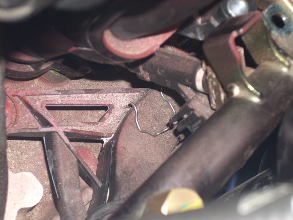
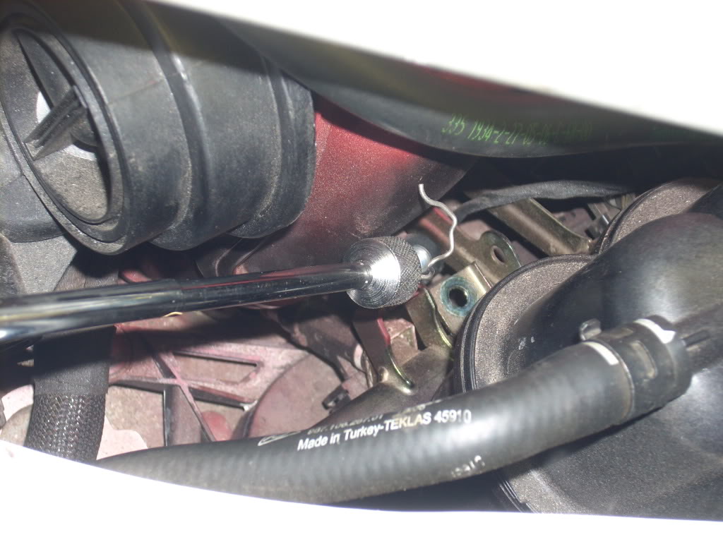
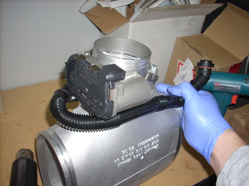
tighten the screw back onto the ground post so that the line is now on the opposite side.
next mount the GT3 Throttlebody onto the X51 plenum, the cayman S screws work perfect.
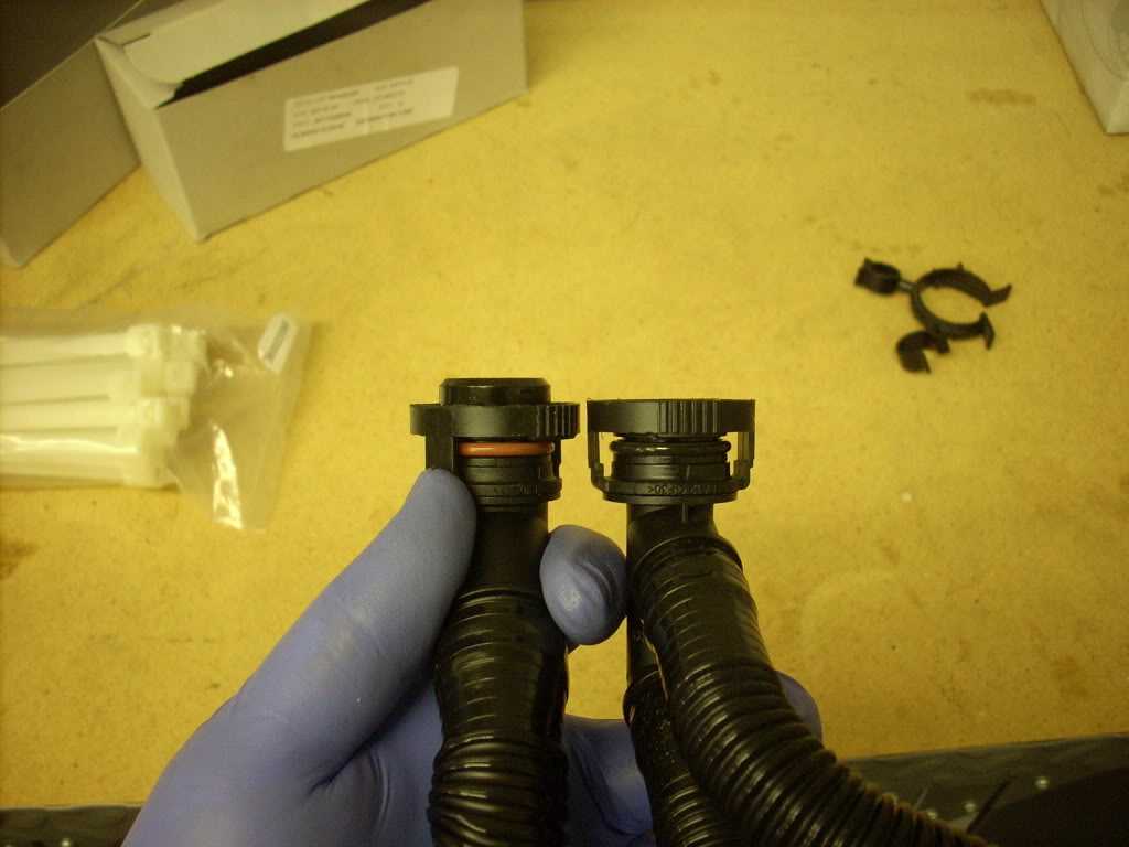
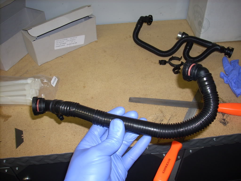
the X51 TB hose will have to be filed down to fit the cayman. Here you can see about a quarter inch needs to be filed.
X51 on the left. stock Cayman on the right.
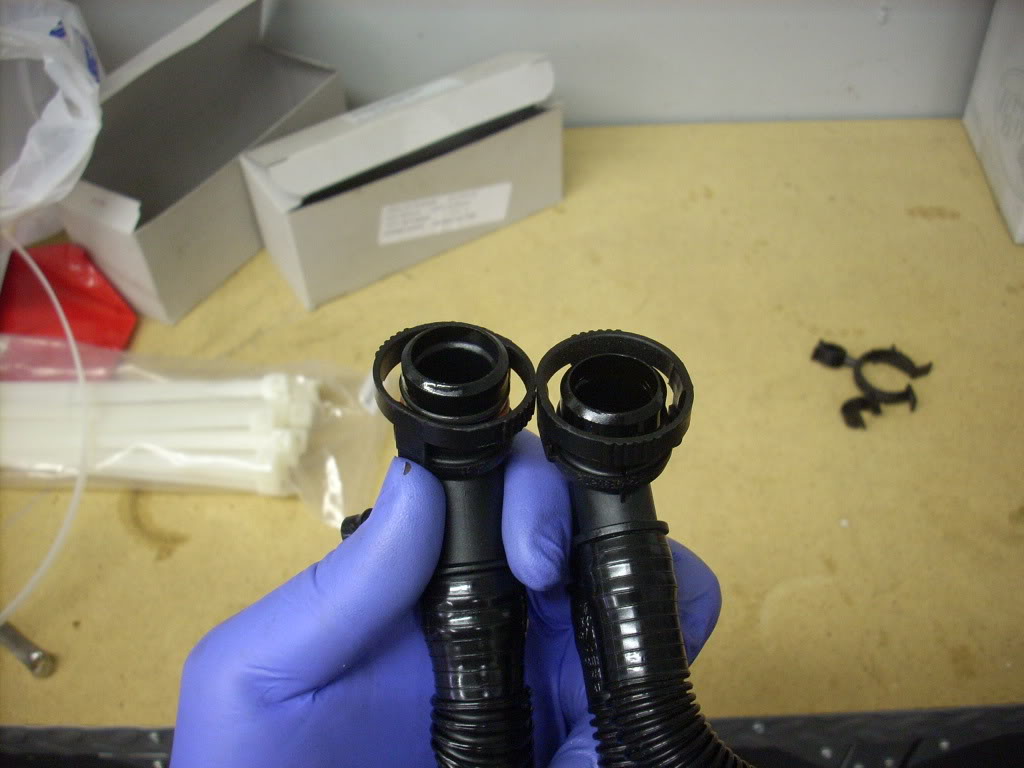
use a file for this part
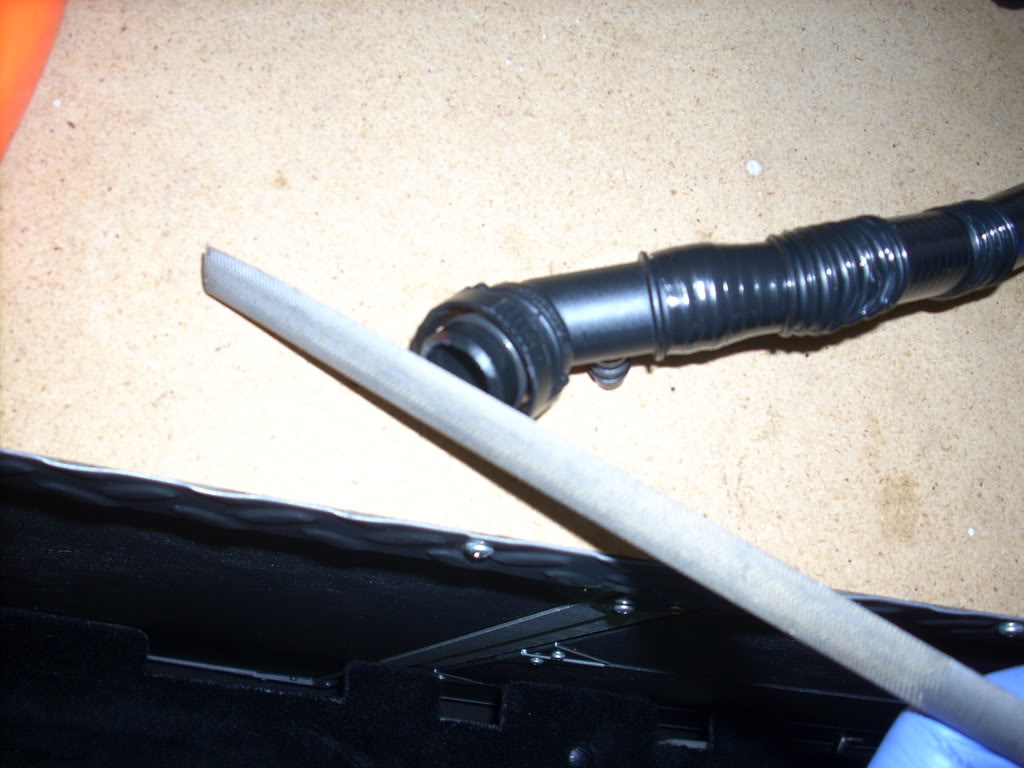
once you've got it filed down use a razor to bevel the edges
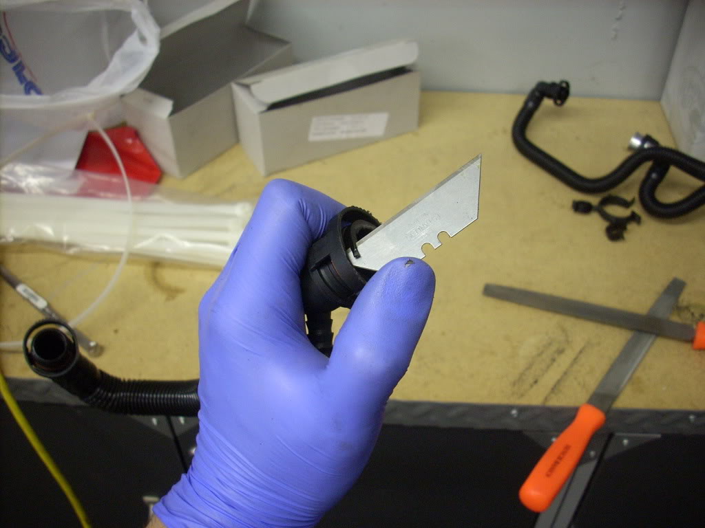
remember you only need to do this on the side that goes to the Cayman "air breather?"
(pics shows hose already reshaped)
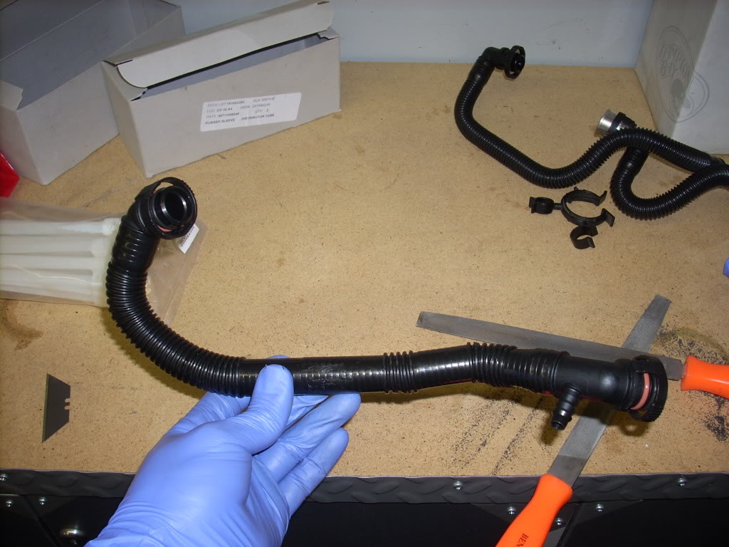
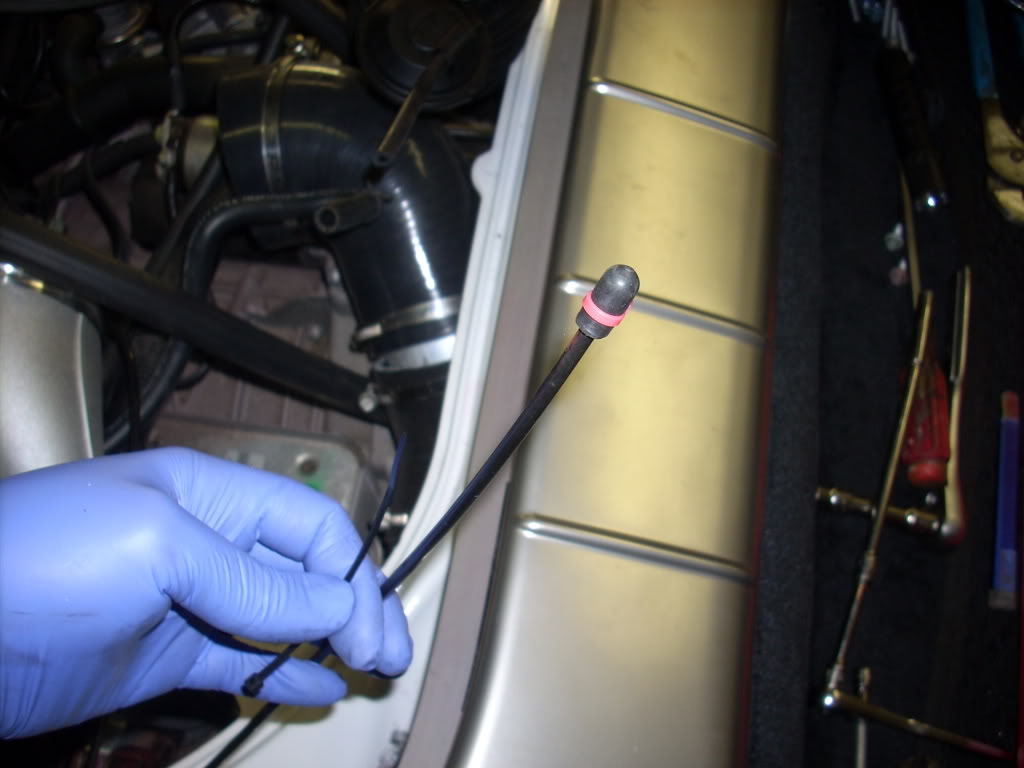
What you will have to do next is heat up the X51 breather hose to form the correct shape. Use a heat on for this
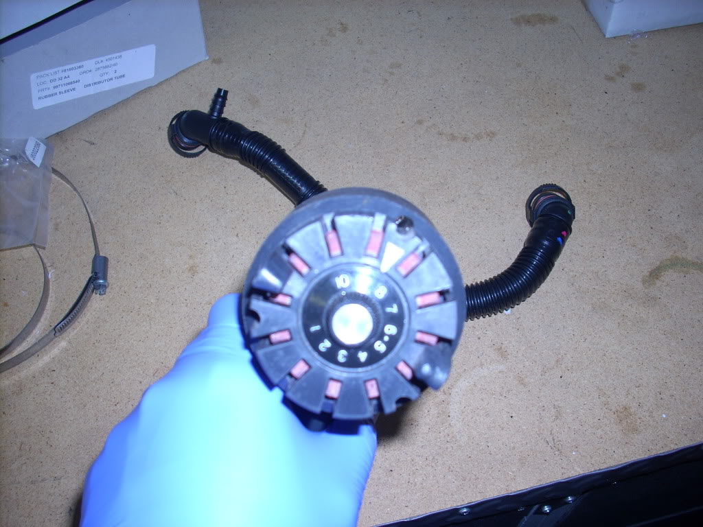
don't leave it on too long just until it gets warm
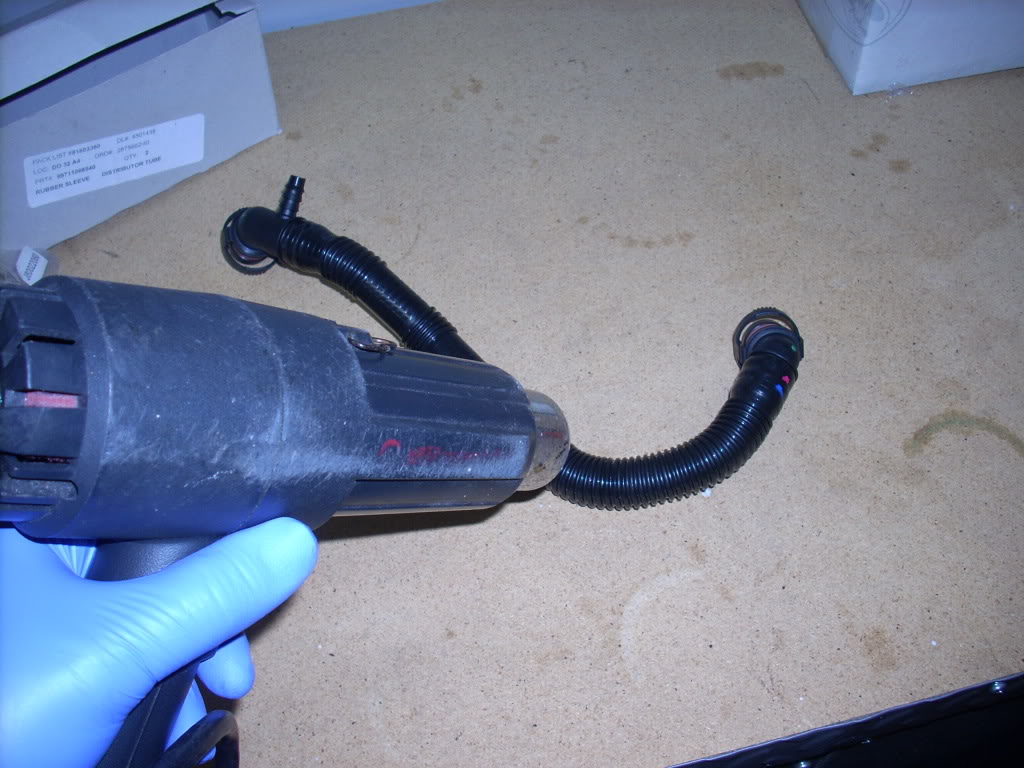
then you want to quickly snap it on and stretch the hose to the opposite side under the TB
hold it there until it cools down, reheat it if necessary to stretch more, be careful, not too much.
it should stay in place if done correctly, I am eventually swapping this part out with a samco silicone hose.
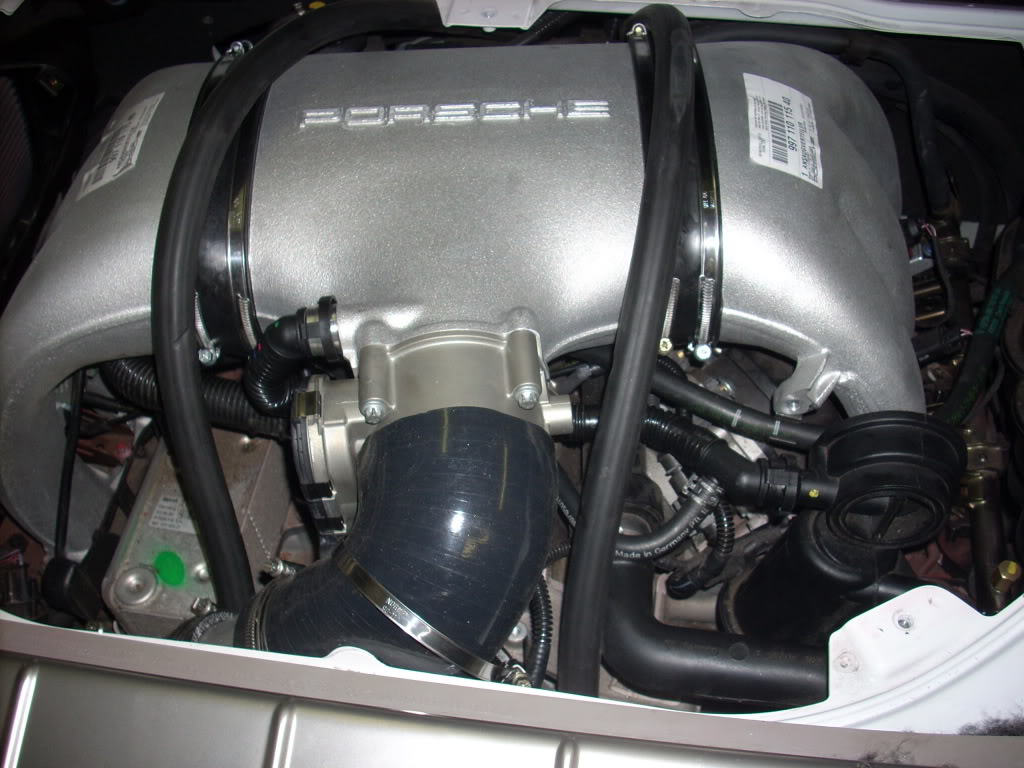
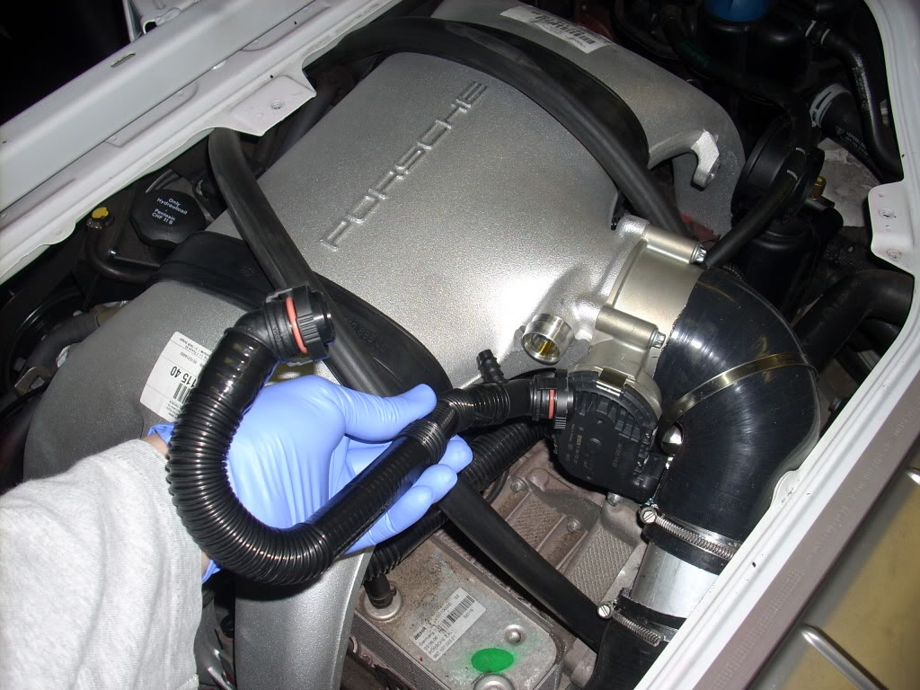
now put in the plenum and TB with the TB GT3 hose on, make sure your sleeves to hold the plenum are in first with the straps, connect the electrical clip to the TB

make sure the sleeves are line up correctly, there should be a gap between the plenum and manifolds
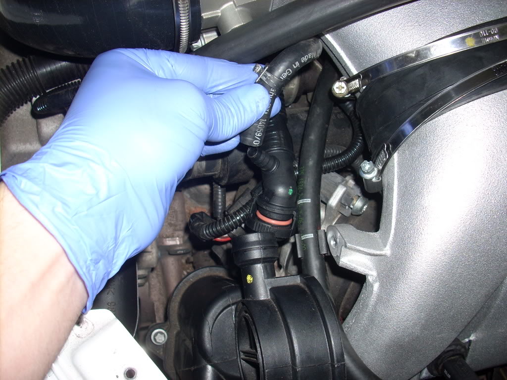
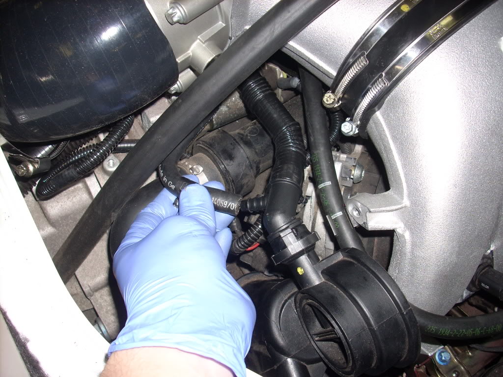
connect the oil collector hose which was on the bottom of the plenum to the x51 hose which is now relocated
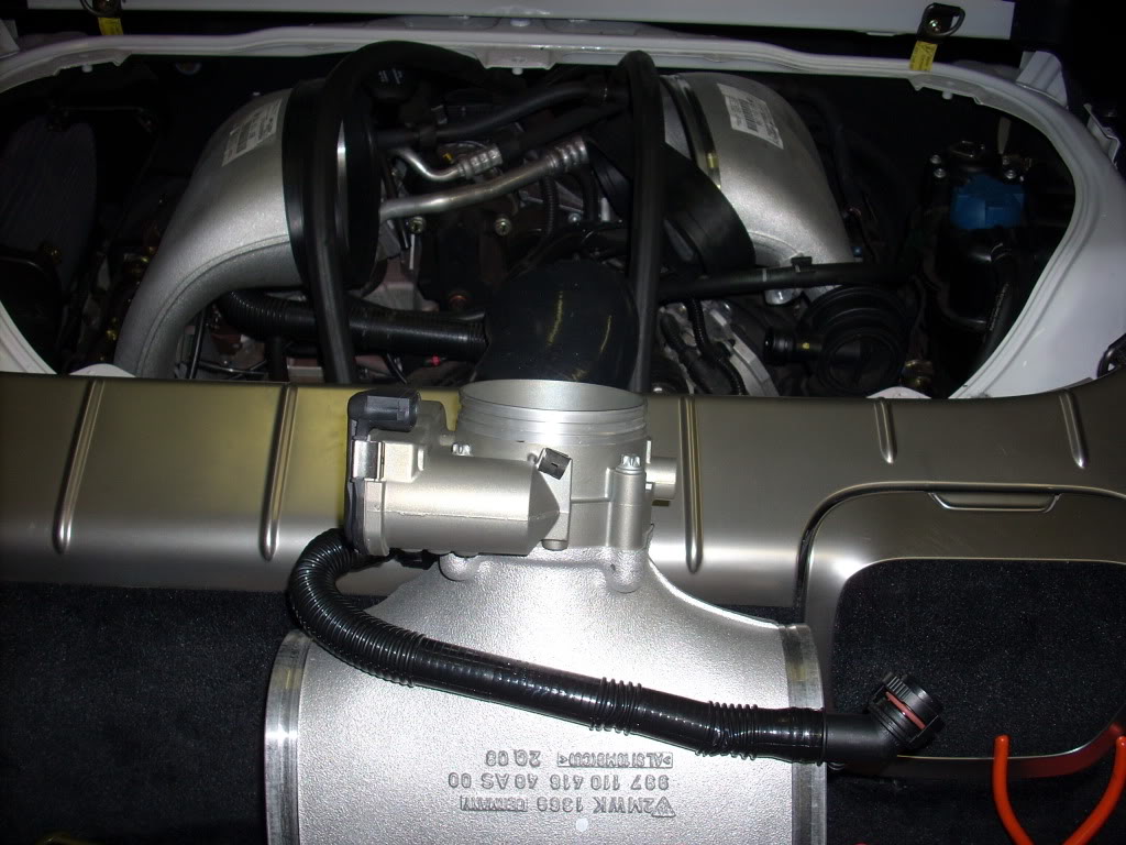
tighten the straps down and it should look like this once together
tighten the GT3 TB strap and push in the metal sleeve to connect the 90deg TB hose to the MAF
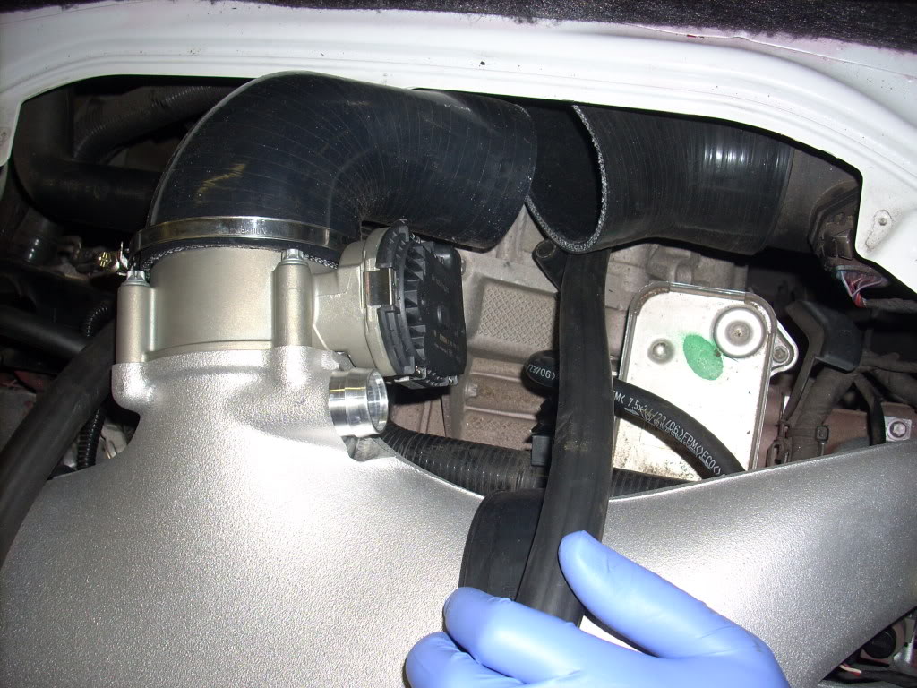
bend up this tab, so that it doesn't collapse the wall of the TB hose
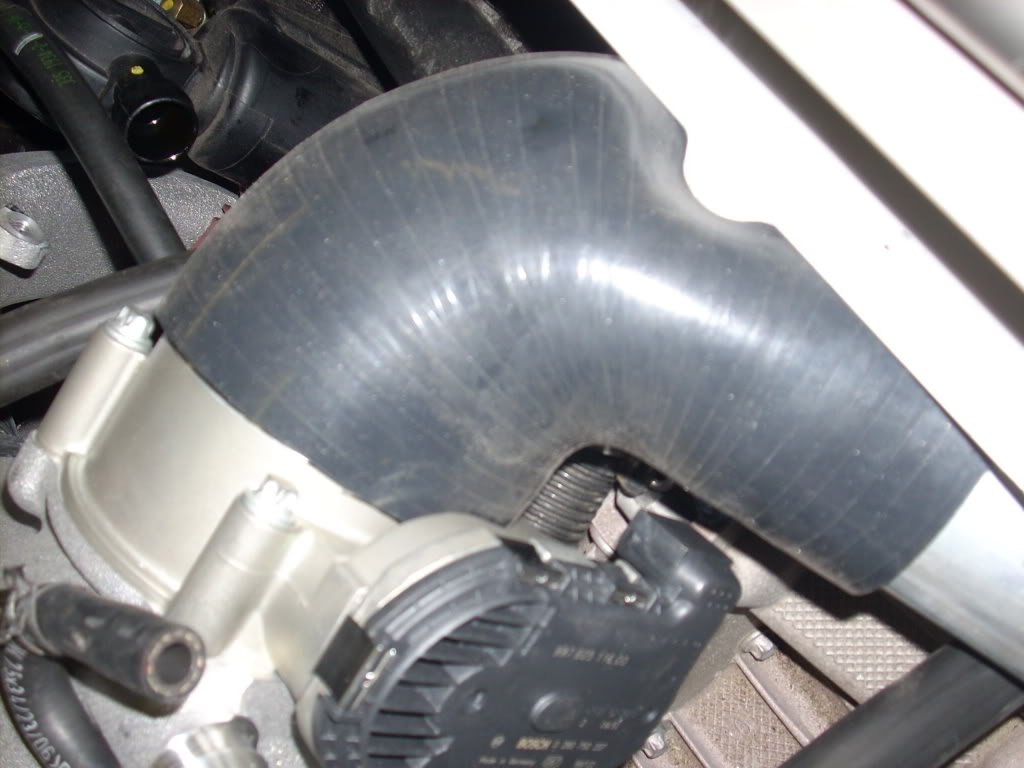
I had removed the reshaped hose to access the MAF better, so if you did the same just put it back in
next mount the GT3 Throttlebody onto the X51 plenum, the cayman S screws work perfect.
the X51 TB hose will have to be filed down to fit the cayman. Here you can see about a quarter inch needs to be filed.
X51 on the left. stock Cayman on the right.
use a file for this part
once you've got it filed down use a razor to bevel the edges
remember you only need to do this on the side that goes to the Cayman "air breather?"
(pics shows hose already reshaped)
What you will have to do next is heat up the X51 breather hose to form the correct shape. Use a heat on for this
don't leave it on too long just until it gets warm
then you want to quickly snap it on and stretch the hose to the opposite side under the TB
hold it there until it cools down, reheat it if necessary to stretch more, be careful, not too much.
it should stay in place if done correctly, I am eventually swapping this part out with a samco silicone hose.
now put in the plenum and TB with the TB GT3 hose on, make sure your sleeves to hold the plenum are in first with the straps, connect the electrical clip to the TB
make sure the sleeves are line up correctly, there should be a gap between the plenum and manifolds
connect the oil collector hose which was on the bottom of the plenum to the x51 hose which is now relocated
tighten the straps down and it should look like this once together
tighten the GT3 TB strap and push in the metal sleeve to connect the 90deg TB hose to the MAF
bend up this tab, so that it doesn't collapse the wall of the TB hose
I had removed the reshaped hose to access the MAF better, so if you did the same just put it back in
Thread Starter
|
Registered User
Joined: Oct 2007
Posts: 292
From: MD
Rep Power: 42
X51 install part 5
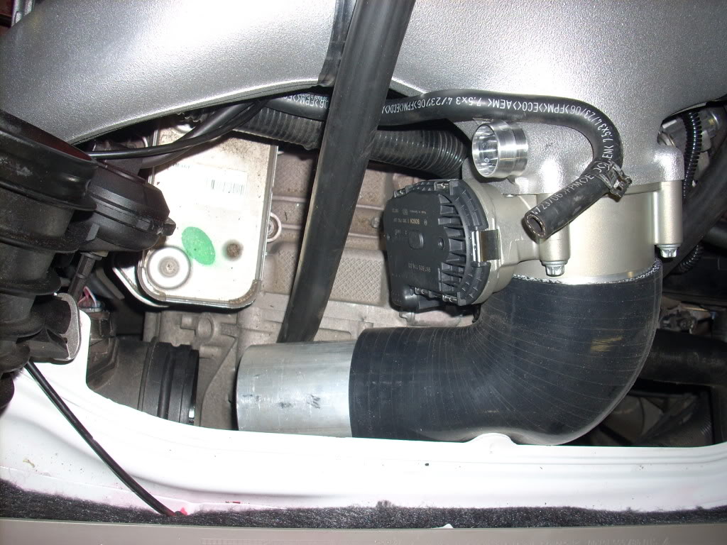
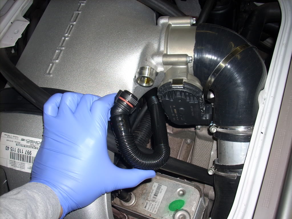
you can see how the stainless steel sleeve joins the MAF and TB, I already have a solid piece on order.
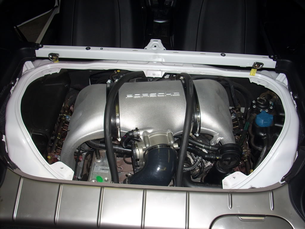
you are almost done.
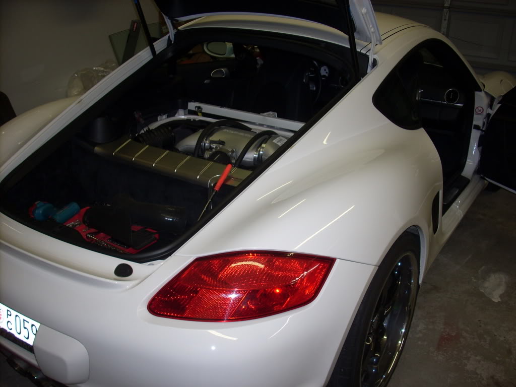
put both of the engine covers back on.
I did not have software so I was curious to see if the car would run. It does run, but once I hit 3500rpm the car would loose power. You need to upload the X51 file from Scott PCA Tech.
now you are done!
*This is still in the R&D stages so far there has been a 8-12WHP increase on MY car which is modded. I would love to try this on a stock Cayman S. I am sure the Power increases will be greater. Engine internals are next.
you are almost done.
put both of the engine covers back on.
I did not have software so I was curious to see if the car would run. It does run, but once I hit 3500rpm the car would loose power. You need to upload the X51 file from Scott PCA Tech.
now you are done!
*This is still in the R&D stages so far there has been a 8-12WHP increase on MY car which is modded. I would love to try this on a stock Cayman S. I am sure the Power increases will be greater. Engine internals are next.

Thread
Thread Starter
Forum
Replies
Last Post
eclip5e
Automobiles For Sale
6
Jul 29, 2019 11:13 AM
joseph_number1
Automotive Parts & Accessories For Sale/Wanted
12
Jul 19, 2018 05:45 PM
turbotuner20v
Automobiles For Sale
20
Sep 11, 2015 12:02 PM

