When you click on links to various merchants on this site and make a purchase, this can result in this site earning a commission. Affiliate programs and affiliations include, but are not limited to, the eBay Partner Network.
After 4 years of DIYs, these power supplies have gotten ridiculously expensive. There are plenty of other options to go with. Just MAKE SURE you know how to remove the over voltage protection.
I just bought two refurbished HP 750watt power supplies on Amazon for $29. The specific model number is HSTNS-PLI8. *MAKE SURE* you get the exact model. There is a DIY to set the output voltage to 13.8V.
This thread discusses modifications: https://www.eevblog.com/forum/projec...-psu-to-13-8v/
This original DIY blog post for the over voltage mod in French is excellent, great pictures. (you can easily translate it using your browser - google translate, built in Safari translate etc.) https://on5vl.org/alimentation-petit-prix/
UPDATE: This definitely works, but the mod requires removing a very small surface mount resistor and bridging across it. It's doable with a small soldering iron if you have very steady hands and are careful. Just be certain you have the right component when you remove it - very easy to get confused and/or dislodge other components while you're trying to remove the part you need to.
UPDATE2: I had some trouble getting this working on a 2nd HSTNS-PL18 750W power supply. I'd say don't go with the French site above.
This video goes alot further, includes a demo. the mod is more involved. Check the comments if you're looking for other voltage levels including 13.8V:
There are plenty of these power supplies on eBay in the $20 range. Again, the specific model number is HSTNS-PLI8. *MAKE SURE* you get the exact model.
Did you reconnect the 2 white three prong wire connectors?
Originally Posted by vkb123
I need to give you the background before getting to the DIY so please bear with me...
Many of us now have a PIWIS 2 or PIWIS 3. I “assembled” my PIWIS 2 last year. I downloaded the software on-line (for free!) and then bought a clone Samtec interface from China. The program runs using VMWare on my old MacBook Pro. Windows XP is the operating system so everything is a bit clunky and slow but it works well enough and is perfect for my occasional diagnostic and coding needs! Best of all, my total build cost was crazy cheap! In fact, I sold my Durametric Pro cable after putting together the PIWIS because the PIWIS is a much more powerful tool!
My primarily motivation to get a PIWIS was to lower my car through the air suspension. I was initially looking at lowering using a module ($$$) or using links. I had read that lowering could be done with a PIWIS but there was very little DIY information on-line on how to do this. I have now figured out how to do this and will do up a “DIY Lowering with PIWIS” for the community once I get a chance.
When I first started using my PIWIS I got a low voltage warning even though my battery was fully charged (had been sitting for days on a Porsche Charge-o-mat Pro) and I had my 10A battery charger connected during my PIWIS session. A forum member on Rennlist with extensive PIWIS knowledge posted about the need for “clean” power while using the PIWIS. This ideas of “clean” power intrigued me. This lead me down a “rabbit hole”...
I came across this Porsche After Sales Technical Bulletin confirming the need to use a battery charger with a fixed voltage between 13.5V - 14.5V while ECU programming on modern Porsche vehicles. Porsche recommended using a battery charger capable of putting out a minimum current of 90A to maintain this stable voltage. Few of us have chargers that can produce a STEADY 90A (not a one time boost charge).
So...VOLTAGE needs to stay constant (stable) while ECU coding. To accomplish this, amperage needs to fluctuate to maintain constant voltage. So, using a conventional battery charger that puts out constant amperage doesn’t fit the bill.
I then looked into commercially available power supply units (PSU) that supply constant voltage (i.e. “clean” power). The Schumacher INC100 fits the bill but is crazy expensive! I thought about buying one but, in the end, couldn’t justify the cost for my occasional DIY use.
Then I stumbled across a forum post on BoostAddict that described how to make your own PSU using a computer sever power supply. I went ahead and made my own and it works AMAZINGLY! I’ve used it for hours and the voltage remains rock solid stable with no fluctuation. I guess this shouldn’t be a surprise as it is designed to power computer systems. It is quiet, portable, doesn’t overheat, and it cost me $55 (CDN) all in!
FYI...I did not come up with this PSU build. I’m solely passing along the knowledge I gained as I chased the rabbit down the hole!
Disclaimer: Do this at your own risk and don't mix up the polarity!
So here are the steps:
WHAT YOU NEED:
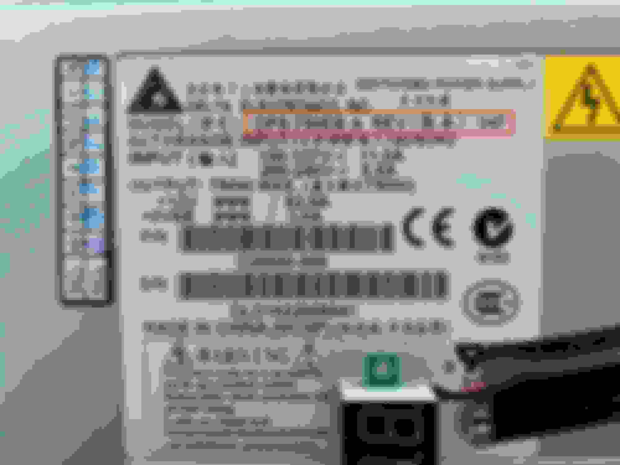
Delta Electronics DPS-750EB (Rev A) server (switching) power supply. Mine has the DC-2173 daughter board. I bought mine off eBay for $25 + shipping:
This power supply also comes with other daughter boards but this DIY works with the DC-2173.
BUILD STEPS:
1. Solder a bridge between pins 70 and 69. Then solder a jumper wire from these connected pins to ground. This will power on the PSU.
2. Solder the 1K ohm resistor between pin 63 and ground. This allows you to adjust the voltage on the PSU (we'll get to that later) into the range we want for coding (~14V).
3. Open these 6 Phillips screws to open the top of the PSU.
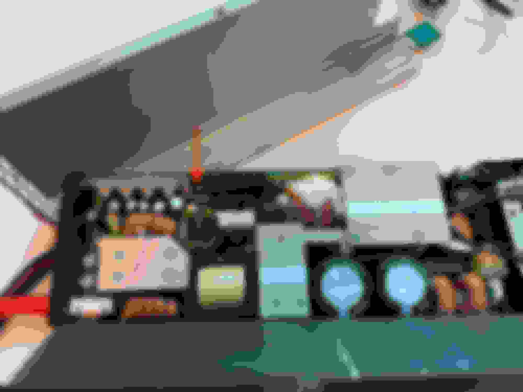
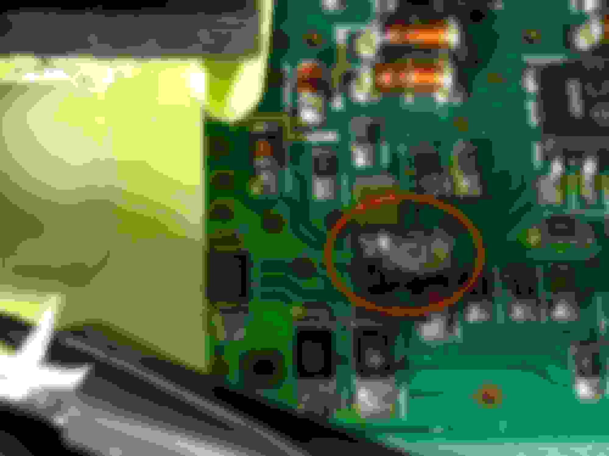
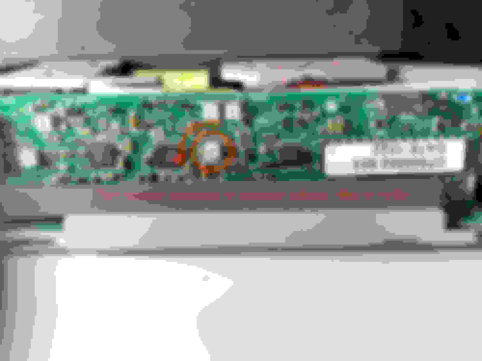
4. Find the DC-2173 daughter board. On the backside of the daughter board (i.e. facing inwards) find the two 3-pronged wire connectors and use a small flathead screwdriver to release them. Identify the area I've circled and solder a bridge between the 2 marked circuits. This allow you to override the over voltage protector (OVP) so that we can turn up the voltage of the PSU from 12V (designed to power a computer) to 14.6V (what we want for coding). NOTE: this OVP override procedure is specific to the DC-2173. If you have a PSU with another daughter board search on-line to find out how to do this step).
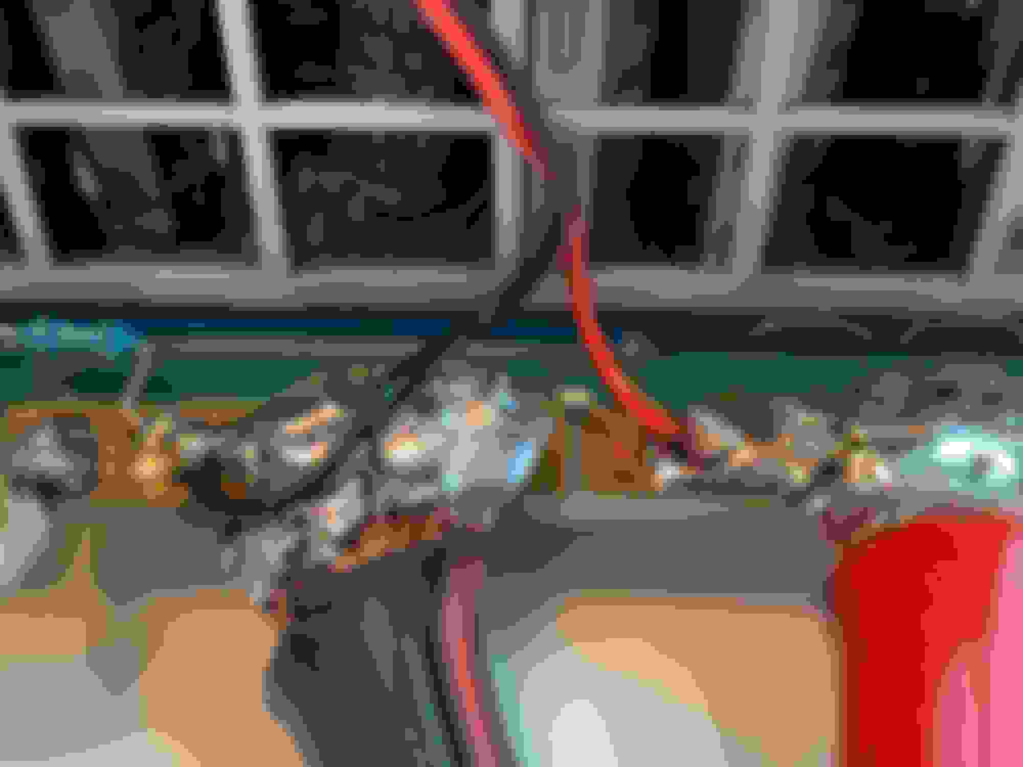
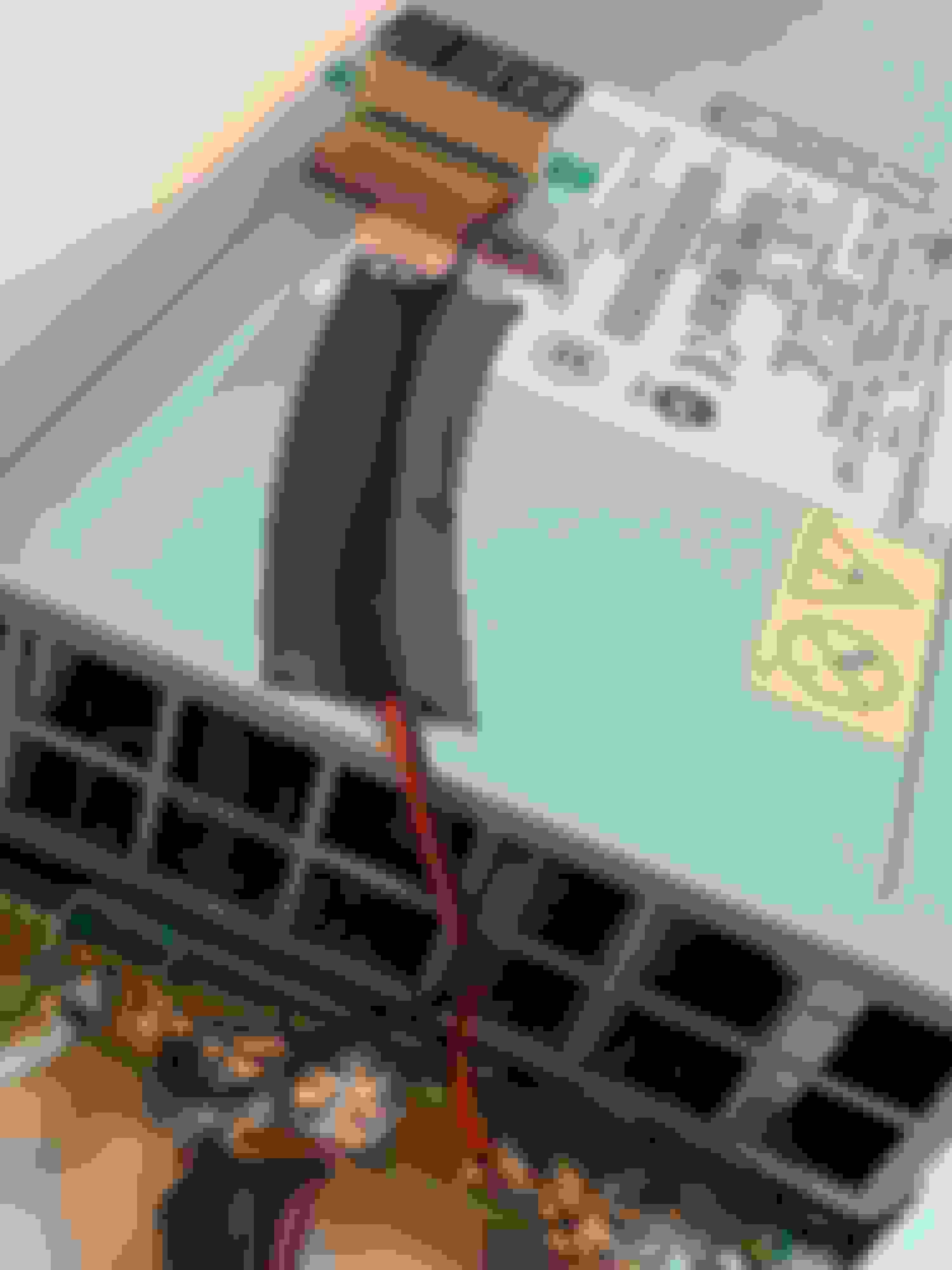
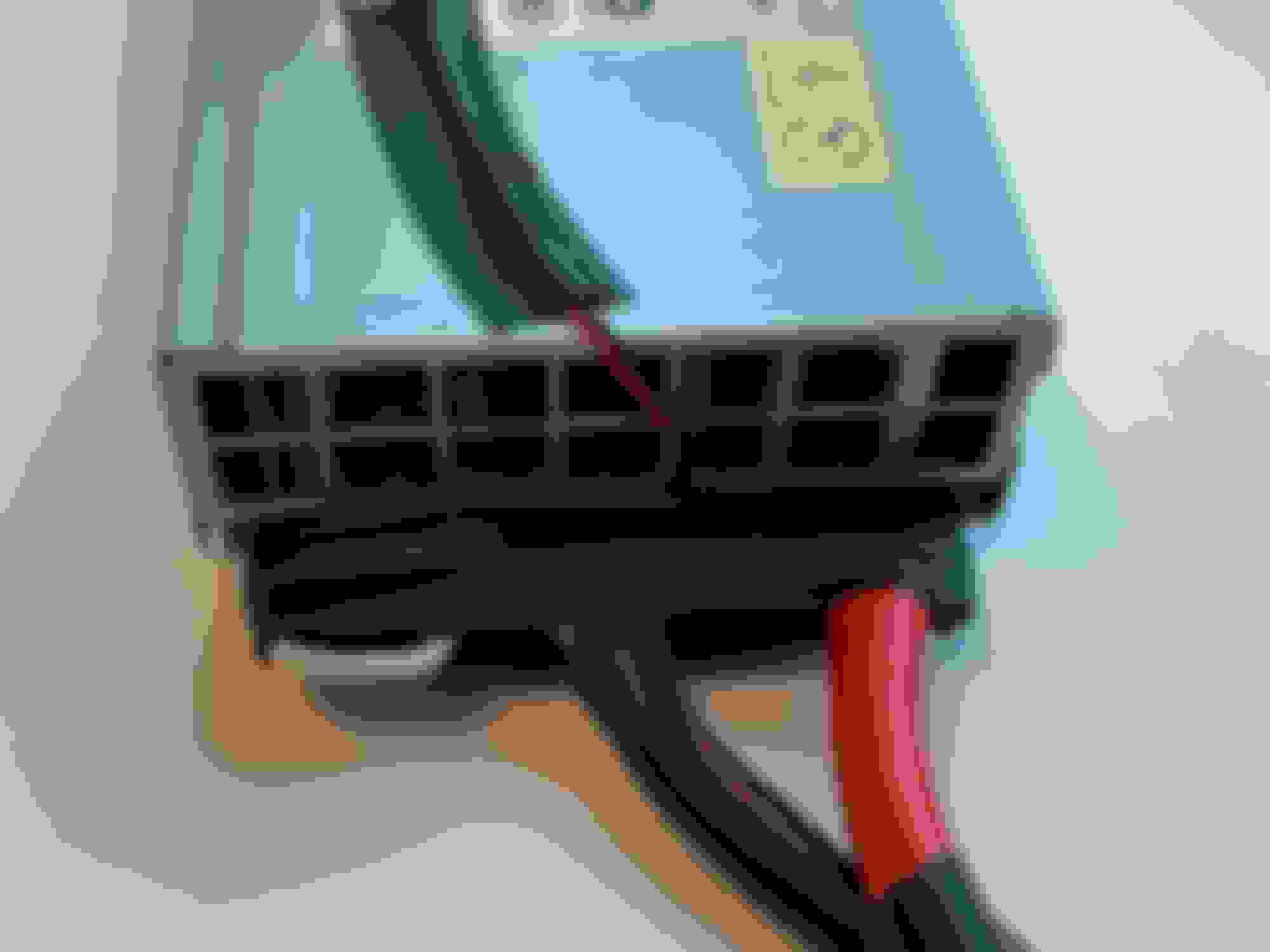
Here are the two 3-pronged connectors that need to be released. Slide a small flathead on top of them to release the clips. Look here to find the circuits that need to be bridged with solder.
Solder a bridge between these two circuits. I used a magnifying glass to do this step as it's SMALL! Solder done!
5. Find this set screw (called the voltage pot) on the "outside" of the DC-2173 daughter board. This allow you to adjust the voltage output of the PSU. When you are looking straight at the DC-2173 daughter board, turning the set screw on the voltage pot clockwise decreases the voltage and counterclockwise increases the voltage.
6. Reconnect the two 3-pronged wire connectors (I forgot to do this initially and couldn't figure out why it wouldn't work!). Close up the top of the PSU.
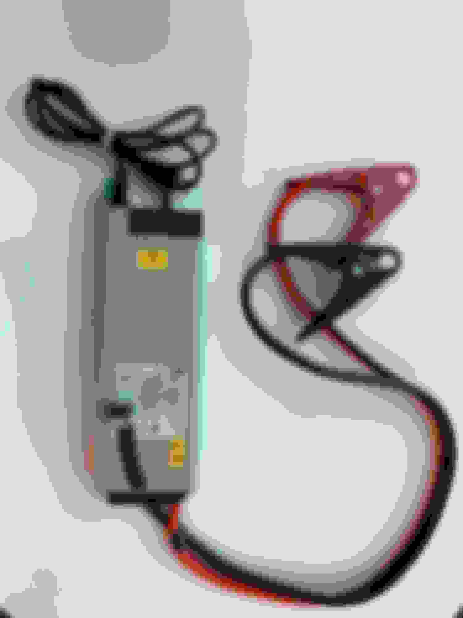
7. Cut the booster cables (give yourself sufficient length) and solder the exposed cables to the positive and negative terminals. I split the wires into a “U” and soldered onto the top and bottom of the terminals.
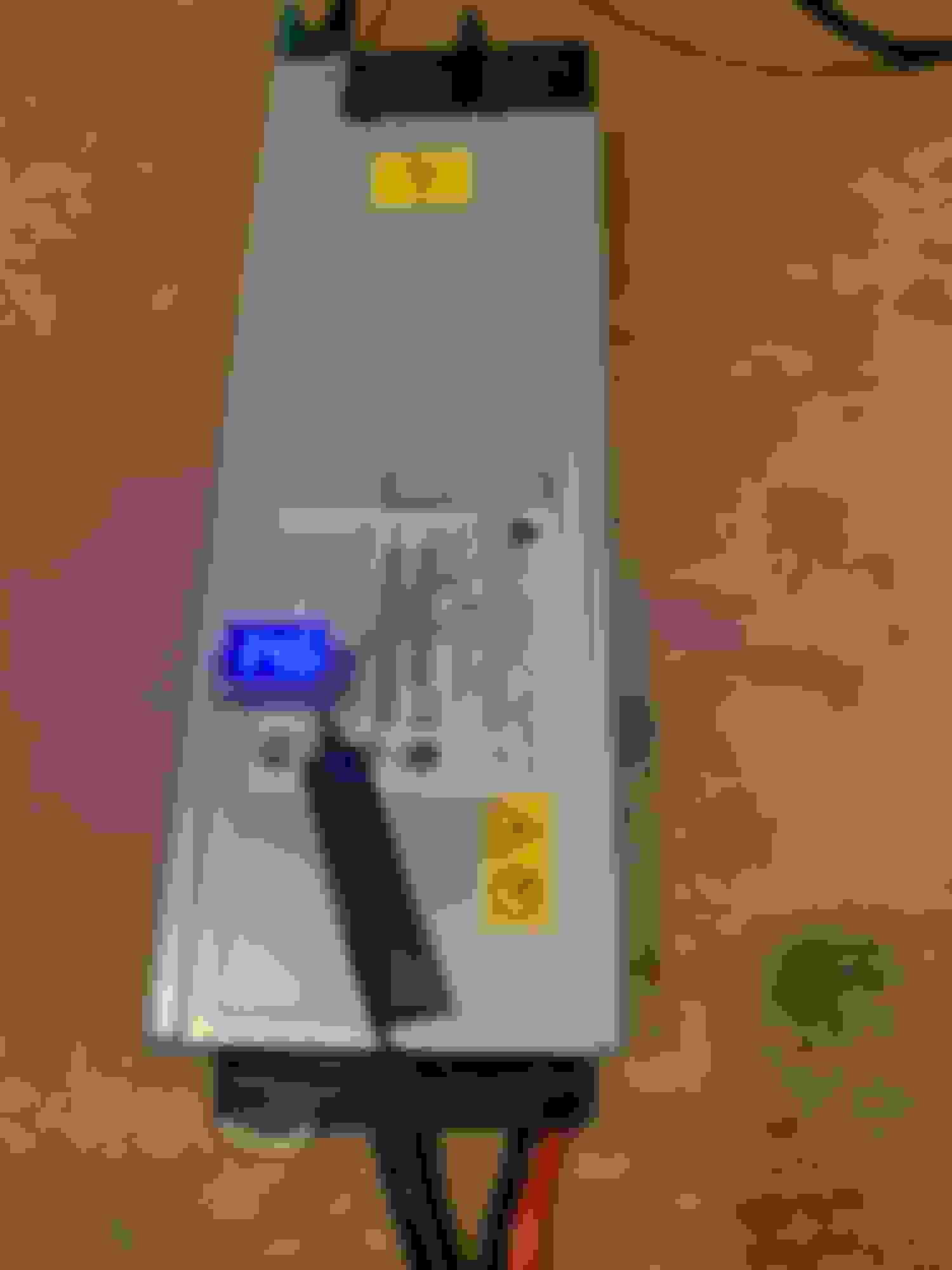
8. I then soldered a mini voltmeter to the positive and negative terminals to see how much power the PSU was putting out.
9. Wrap the exposed connections with electrical tape.
10. DONE!!
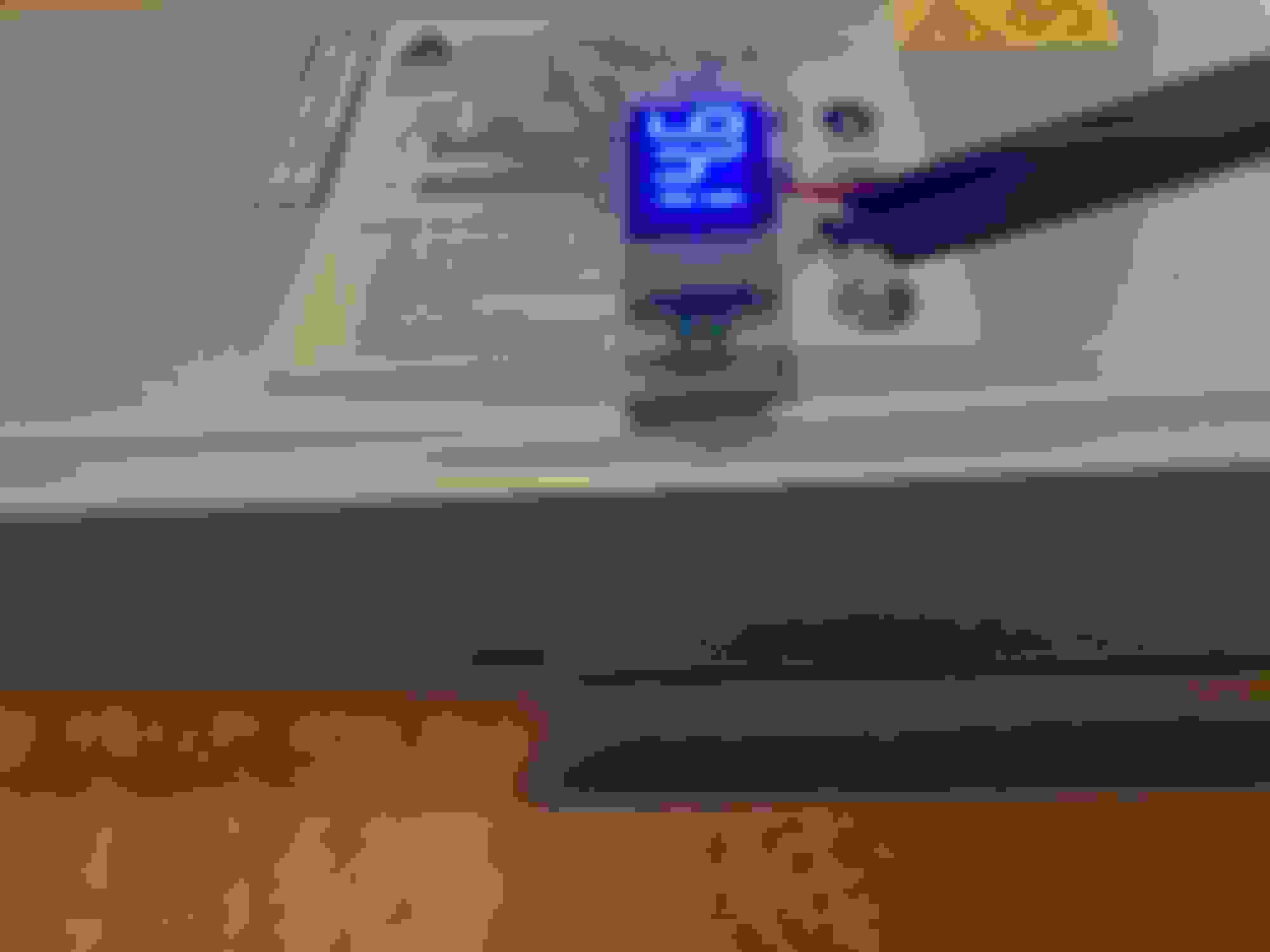
When working with your PIWIS, connect the positive and negative alligator clamps of your new PSU to the battery posts in the engine bay (don't need to connect directly to the battery terminals in the hatch/boot). Plug your PSU into an electrical outlet. The PSU puts out 14.6 volts and when connected to the car the voltage drops to about 14.1V under load. It will maintain this stable "clean" voltage for hours! You can confirm this stable voltage by observing the voltmeter in your instrument cluster. My car voltage stayed fixed at 14.1 for hours while I was using my PIWIS! This is pretty much were we want the voltage for ECU coding!
I attached the mini voltmeter to the PSU case using sticky felt (used for furniture legs) and then velcro tape onto the back of the voltmeter sticking to this felt.
This PSU is an amazing little tool! You now never need to worry about bricking your car's ECU because of a voltage drop while coding!
If this information helped you or you found this thread interesting please consider leaving some +rep points!
Was wondering if you reconnected the 2 white connectors inside the unit. I followed your instructions to the T and it is not letting the voltage go to 14 when connected to the porsche.
Was wondering if you reconnected the 2 white connectors inside the unit. I followed your instructions to the T and it is not letting the voltage go to 14 when connected to the porsche.
Yes. Need to reconnect those 2 small wire harnesses. Good luck!